KINO-780AM2 Motherboard
Page 18
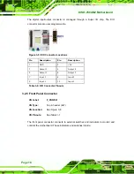
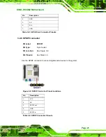
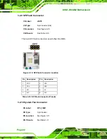
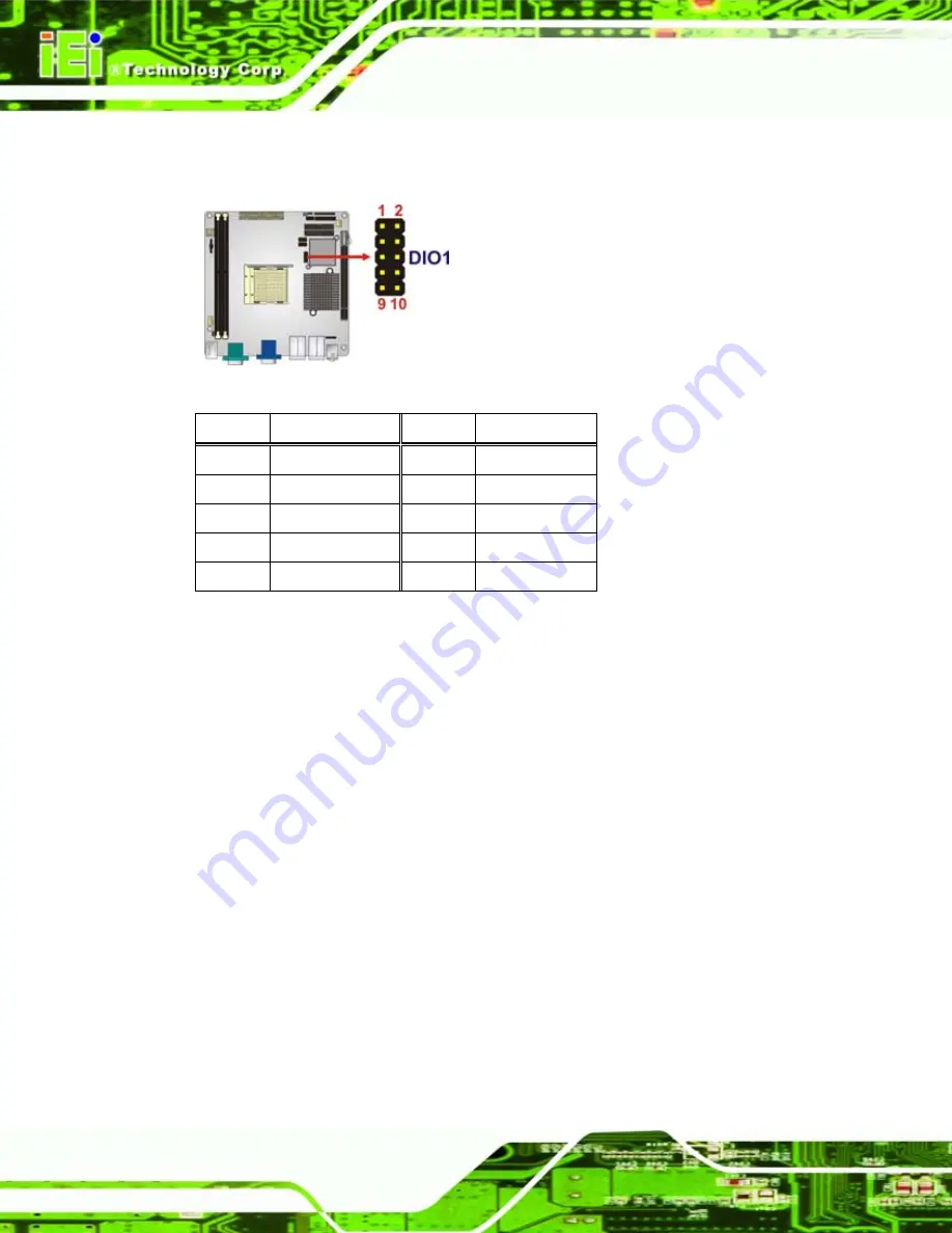
The digital input/output connector is managed through a Super I/O chip. The DIO
connector pins are user programmable.
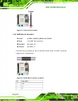
Figure 3-5: DIO Connector Locations
Pin Description Pin Description
1 GND
2 +5V
3 Output
3 4 Output
2
5 Output
1 6 Output
0
7 Input
3
8 Input
2
9
Input 1
10
Input 0
Table 3-6: DIO Connector Pinouts
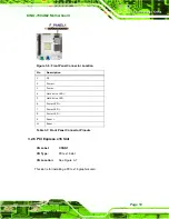
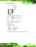
3.2.5 Front Panel Connector
CN Label:
F_PANEL1
CN Type:
14-pin header (2x7)
CN Location:
CN Pinouts:
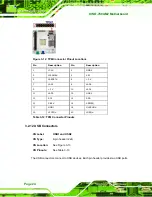
The front panel connector connects to external switches and indicators to monitor and
controls the motherboard. These indicators and switches include:
Summary of Contents for KINO-780AM2
Page 12: ...KINO 780AM2 Motherboard Page xii...
Page 13: ...KINO 780AM2 Motherboard Page 1 Chapter 1 1 Introduction...
Page 16: ...KINO 780AM2 Motherboard Page 4 Figure 1 3 KINO 780AM2 Dimensions mm...
Page 20: ...KINO 780AM2 Motherboard Page 8 Chapter 2 2 Packing List...
Page 24: ...KINO 780AM2 Motherboard Page 12 Chapter 3 3 Connectors...
Page 45: ...KINO 780AM2 Motherboard Page 33 Chapter 4 4 Installation...
Page 70: ...KINO 780AM2 Motherboard Page 58 Chapter 5 5 BIOS...
Page 114: ...KINO 780AM2 Motherboard Page 102 Appendix A A BIOS Options...
Page 117: ...KINO 780AM2 Motherboard Page 105 Load Optimal Defaults 100 Load Failsafe Defaults 101...
Page 118: ...KINO 780AM2 Motherboard Page 106 Appendix B B Terminology...
Page 122: ...KINO 780AM2 Motherboard Page 110 Appendix C C Digital I O Interface...
Page 125: ...KINO 780AM2 Motherboard Page 113 Appendix D D Watchdog Timer...
Page 128: ...KINO 780AM2 Motherboard Page 116 Appendix E E Hazardous Materials Disclosure...


