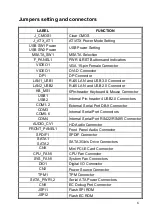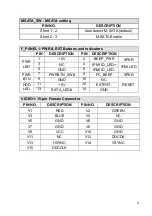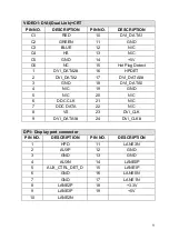
7
CN5
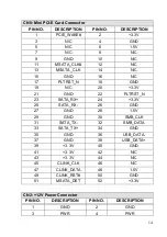
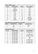
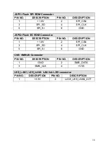
SMBUS Connector
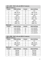
LED_LAN1
LAN1 LINK LED Connector
LED_LAN2
LAN2 LINK LED Connector
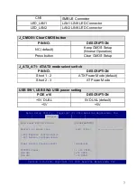
USB SW1, USB SW2: USB power setting
PCIE x16
DESCRIPTION
+5V DUAL
5V DUAL (default)
+5V
+5V
Aptio Setup Utility – Copyright (C) 2012 American Megatrends, Inc.
Chipset
Auto Power Button Status [Disabled(ATX)]
Restore AC Power Loss
[Last State]
> PCI Express Configuration
> PCI Azalia Configuration
Power Saving Function(ERP)
[Disabled]
PCIEX16 Power
[1 x16 PCIE]
USB SW1
[+5V DUAL]
USB SW2
[+5V DUAL]
------------------
Version 2.15.1236. Copyright (C) 2012 American Megatrends, Inc.
J_ATX_AT1: AT/ATX mode select switch
PIN NO.
DESCRIPTION
Short 1 - 2
ATX Power Mode (default)
Short 2 - 3
AT Power Mode
J_CMOS1: Clear CMOS button
PIN NO.
DESCRIPTION
NC (default)
Keep CMOS Setup
(Normal Operation)
Press button
Clear CMOS Setup


