P age 101
K INO-P V-D5253-D4253 Mini-ITX Motherboard
C .2.5
C reate F actory Default Image
NOTE :
Before creating the factory default image, please configure the system
to a factory default environment, including driver and application
installations.
To create a factory default image, please follow the steps below.
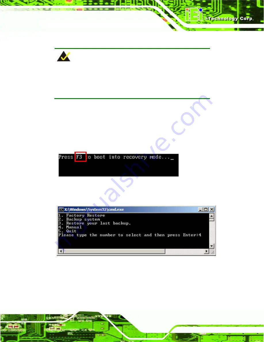
Turn on the system. When the following screen displays (
), press the <
F3
>
key to access the recovery tool. The message will display for 10 seconds,
please press F3 before the system boots into the operating system.
Figure C-10: Press F3 to Boot into Recovery Mode
The recovery tool menu appears. Type <
4
> and press <
Enter
>. (
Figure C-11: Recovery Tool Menu
The About Symantec Ghost window appears. Click
OK
button to continue.
Summary of Contents for KINO-PV-D5253-D4253
Page 12: ......
Page 13: ...Page 1 K INO PV D5253 D4253 Mini ITX Motherboard Chapter 1 1 Introduction...
Page 20: ...Page 8 K INO PV D5253 D4253 Mini ITX Motherboard Chapter 2 2 Packing Lis t...
Page 25: ...Page 13 K INO PV D5253 D4253 Mini ITX Motherboard Chapter 3 3 Connectors...
Page 49: ...Page 37 K INO PV D5253 D4253 Mini ITX Motherboard Chapter 4 4 Ins tallation...
Page 65: ...Page 53 K INO PV D5253 D4253 Mini ITX Motherboard Chapter 5 5 B IOS...
Page 95: ...Page 83 K INO PV D5253 D4253 Mini ITX Motherboard Appendix A A B IOS Options...
Page 98: ...Page 86 K INO PV D5253 D4253 Mini ITX Motherboard Appendix B B Terminology...
Page 102: ...Page 90 K INO PV D5253 D4253 Mini ITX Motherboard Appendix C C One K ey R ecovery...
Page 109: ...Page 97 K INO PV D5253 D4253 Mini ITX Motherboard Figure C 5 Partition Creation Commands...
Page 130: ...Page 118 K INO PV D5253 D4253 Mini ITX Motherboard Appendix D D Watchdog Timer...
Page 133: ...Page 121 K INO PV D5253 D4253 Mini ITX Motherboard Appendix E E Digital I O Interface...


