NANO-GM45A2 EPIC SBC
Page 20
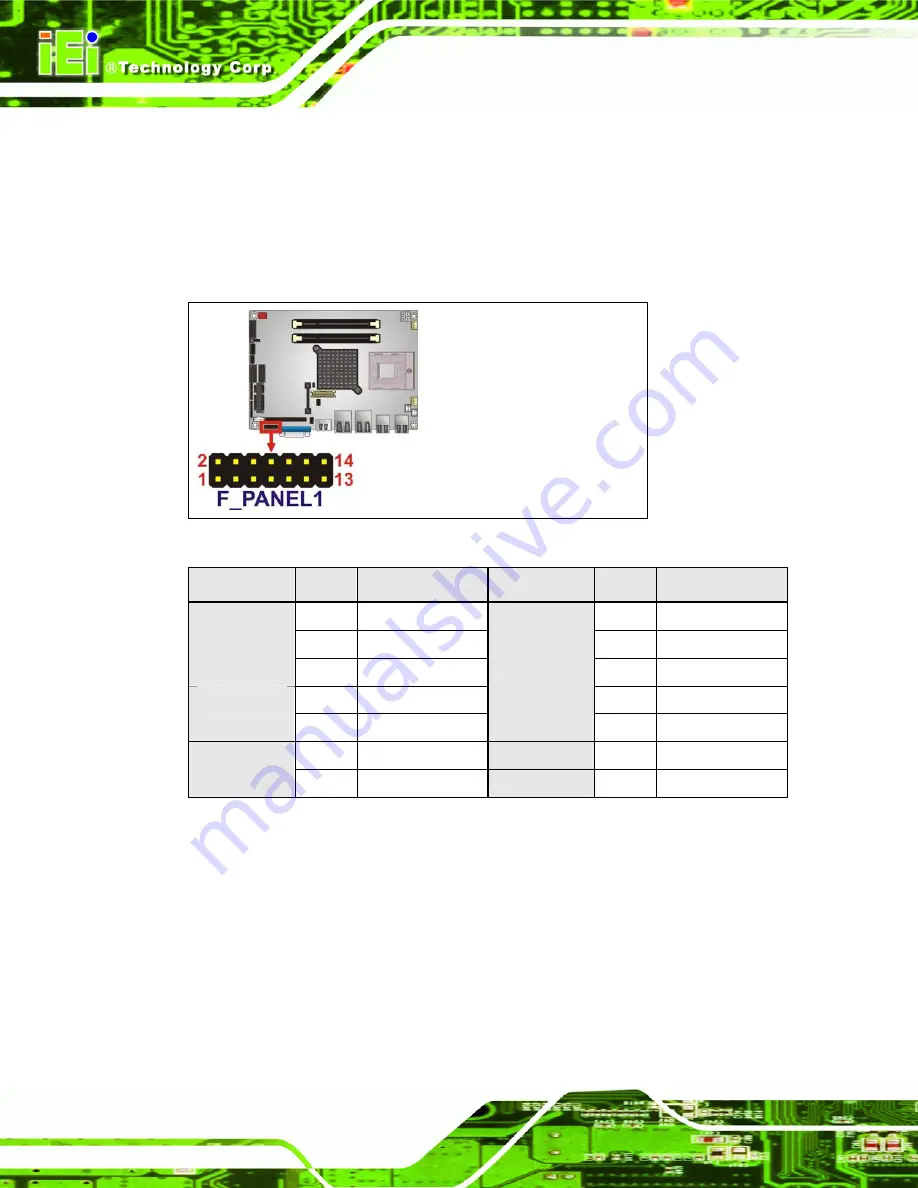
The front panel connector connects to external switches and indicators to monitor and
controls the motherboard. These indicators and switches include:
Power
button
Reset
Power
LED
HDD
LED
Figure 3-7: Front Panel Connector Location
FUNCTION
PIN
DESCRIPTION
FUNCTION
PIN
DESCRIPTION
1 +V5S
2 +V5S
3 N/C
4 N/C
Power LED
5 GND
6 N/C
7 PWR_BT#
8 PC_BEEP
Power Button
9 GND
System
Beeper
10 N/C
11 +V5S
Reset 12
PM_SYSRST#
HDD LED
13 SB_SATA_LED 14
GND
Table 3-8: Front Panel Connector Pinouts
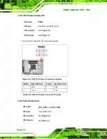
3.2.7 IEEE 1394a Connectors
CN Label:
IEEE1
and
IEEE2
CN Type:
8-pin header (1x8)
CN Location:
See
5
Figure 3-8
CN Pinouts:
See
5
Table 3-9
Summary of Contents for NANO-GM45A2
Page 2: ...NANO GM45A2 EPIC SBC Page II Revision Date Version Changes 5 May 2010 1 00 Initial release ...
Page 13: ...NANO GM45A2 EPIC SBC Page 1 Chapter 1 1 Introduction ...
Page 20: ...NANO GM45A2 EPIC SBC Page 8 Chapter 2 2 Unpacking ...
Page 24: ...NANO GM45A2 EPIC SBC Page 12 Chapter 3 3 Connectors ...
Page 46: ...NANO GM45A2 EPIC SBC Page 34 Chapter 4 4 Installation ...
Page 73: ...NANO GM45A2 EPIC SBC Page 61 Chapter 5 5 BIOS Screens ...
Page 107: ...NANO GM45A2 EPIC SBC Page 95 Appendix A A BIOS Menu Options ...
Page 110: ...NANO GM45A2 EPIC SBC Page 98 Appendix B B One Key Recovery ...
Page 116: ...NANO GM45A2 EPIC SBC Page 104 Figure B 3 Partition Creation Commands ...
Page 133: ...NANO GM45A2 EPIC SBC Page 121 Appendix C C Terminology ...
Page 138: ...NANO GM45A2 EPIC SBC Page 126 Appendix D D Watchdog Timer ...
Page 141: ...NANO GM45A2 EPIC SBC Page 129 Appendix E E Compatibility ...
Page 145: ...NANO GM45A2 EPIC SBC Page 133 Appendix F F Hazardous Materials Disclosure ...


