NANO-ULT3 SBC
Page 20
CN Pinouts:
See
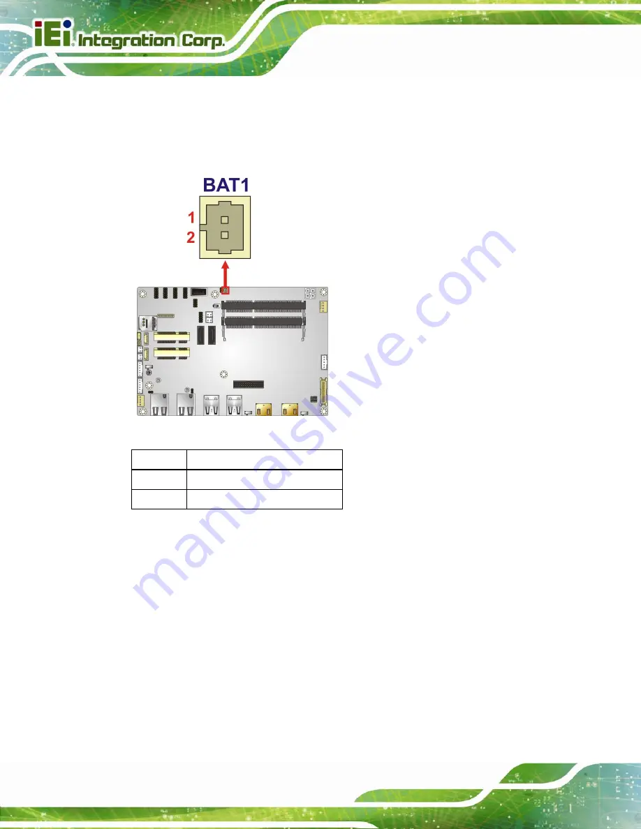
The battery connector is connected to the system battery. The battery provides power to
the system clock to retain the time when power is turned off.
Figure 3-4: Battery Connector Location
Pin Description
1
VBAT+
2 GND
Table 3-5: Battery Connector Pinouts
3.2.4 Buzzer Connector
CN Label:
SP1
CN Type:
2-pin wafer, p=1.25 mm
CN Location:
See
CN Pinouts:
See
The buzzer connector is connected to the buzzer.
Summary of Contents for NANO-ULT3
Page 2: ...NANO ULT3 SBC Page II Revision Date Version Changes May 26 2016 1 00 Initial release ...
Page 14: ......
Page 15: ...NANO ULT3 SBC Page 1 Chapter 1 1 Introduction ...
Page 24: ...NANO ULT3 SBC Page 10 Chapter 2 2 Unpacking ...
Page 28: ...NANO ULT3 SBC Page 14 Chapter 3 3 Connectors ...
Page 60: ...NANO ULT3 SBC Page 46 Chapter 4 4 Installation ...
Page 77: ...NANO ULT3 SBC Page 63 Figure 4 18 Motherboard Installation Example ...
Page 84: ...NANO ULT3 SBC Page 70 Chapter 5 5 BIOS ...
Page 124: ...NANO ULT3 SBC Page 110 Chapter 6 6 Software Drivers ...
Page 128: ...NANO ULT3 SBC Page 114 Appendix A A Regulatory Compliance ...
Page 130: ...NANO ULT3 SBC Page 116 B Product Disposal Appendix B ...
Page 132: ...NANO ULT3 SBC Page 118 Appendix C C BIOS Menu Options ...
Page 135: ...NANO ULT3 SBC Page 121 Appendix D D Terminology ...
Page 140: ...NANO ULT3 SBC Page 126 Appendix E E Digital I O Interface ...
Page 143: ...NANO ULT3 SBC Page 129 Appendix F F Watchdog Timer ...
Page 146: ...NANO ULT3 SBC Page 132 Appendix G G Hazardous Materials Disclosure ...


