PAC-1700G QIG IEI Technology Corp. Page 7
NOTE:
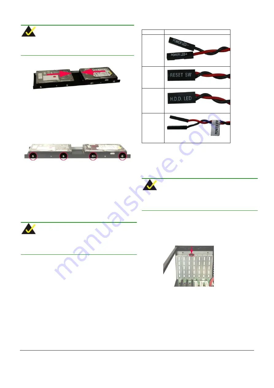
When the 3.5” HDD is installed, make sure both the power socket
and the IDE/SATA connector face inwards.
Figure 21: 3.5
"
HDD Power Sockets and IDE/SATA Connectors
Directions
Step 4:
Align the 3.5” HDD retention screw holes with the
retention screw holes on the sides of the 3.5” HDD
bracket.
Step 5:
To secure the 3.5” HDD to the 3.5” HDD bracket, insert
four retention screws, two into each side of the HDD.
Figure 22: 3.5
"
HDD Retention Screws
Step 6:
Reinstall the 3.5” HDD bracket with the HDD and
reinsert the four previously removed 3.5” HDD bracket
retention screws.
Step 7:
Connect the 3.5” HDD power cable and the IDE/SATA
connector ribbon cable.
Step 0:
STEP 10: CABLING
NOTE:
The cables must be connected to the CPU card before CPU card
installation due to the limitation of the space.
The PAC-1700G has LEDs, buttons and power switch on the front
panel:
o
1 x Power LED
o
1 x HDD LED
o
1 x Power switch
o
1 x Reset button
These components are all connected to the CPU card with cables. To
correctly connect these cables, please refer to the technical
documentation that came with your CPU card. The connectors that are
provided with the chassis are listed below.
No. Name
1
Power LED cable
1
Reset Switch cable
1
HDD LED cable
1
Power switch cable
Table 4: Chassis Connectors
STEP 11: CPU CARD INSTALLATION
To install a CPU card, please follow the instructions below:
NOTE:
The cables must be connected to the CPU card before CPU card
installation due to the limitation of the space.
Step 1:
Connect the HDD cables, FDD cables and power cables
to the CPU card.
Step 2:
Remove the slot cover at the back of the chassis. To do
this, remove the slot cover retention screw at the top of
the slot cover.
Figure 23: Remove the Slot Cover Retention Screw
Step 3:
Slide CPU card into the socket on the backplane
reserved for the CPU card. Make sure the back edge of
the full-size CPU card slots into the corresponding card
guide located at the front of the chassis.


