PAC-400AI QIG
IEI Integration Corp.
3
INSTALLATION STEPS
To install the PAC-400AI chassis, the following installation steps
must be completed:
Step 1:
Unpack the chassis.
Step 2:
Remove the cover.
Step 3:
Install the PSU.
Step 4:
Install the HDD.
Step 5:
Reinstall the upper compartment.
Step 6:
Install the backplane.
Step 7:
Connect the cables.
Step 8:
Install the CPU card.
Step 9:
Install the PCI and ISA expansion cards.
Step 10:
Reinstall the top cover.
Step 11:
Install the wall-mount plates.
Step 0:
The installation steps outlined above are described in detail below.
Please refer to the relevant section.
STEP 1: UNPACK
The PAC-400AI is shipped in a plastic bag that is placed inside a
cardboard box. The items are also shipped with the chassis. When
you unpack the chassis you must:
Make sure all the items listed in the
PACKING LIST
section are present.
Make sure the chassis has not been damaged in any
way.
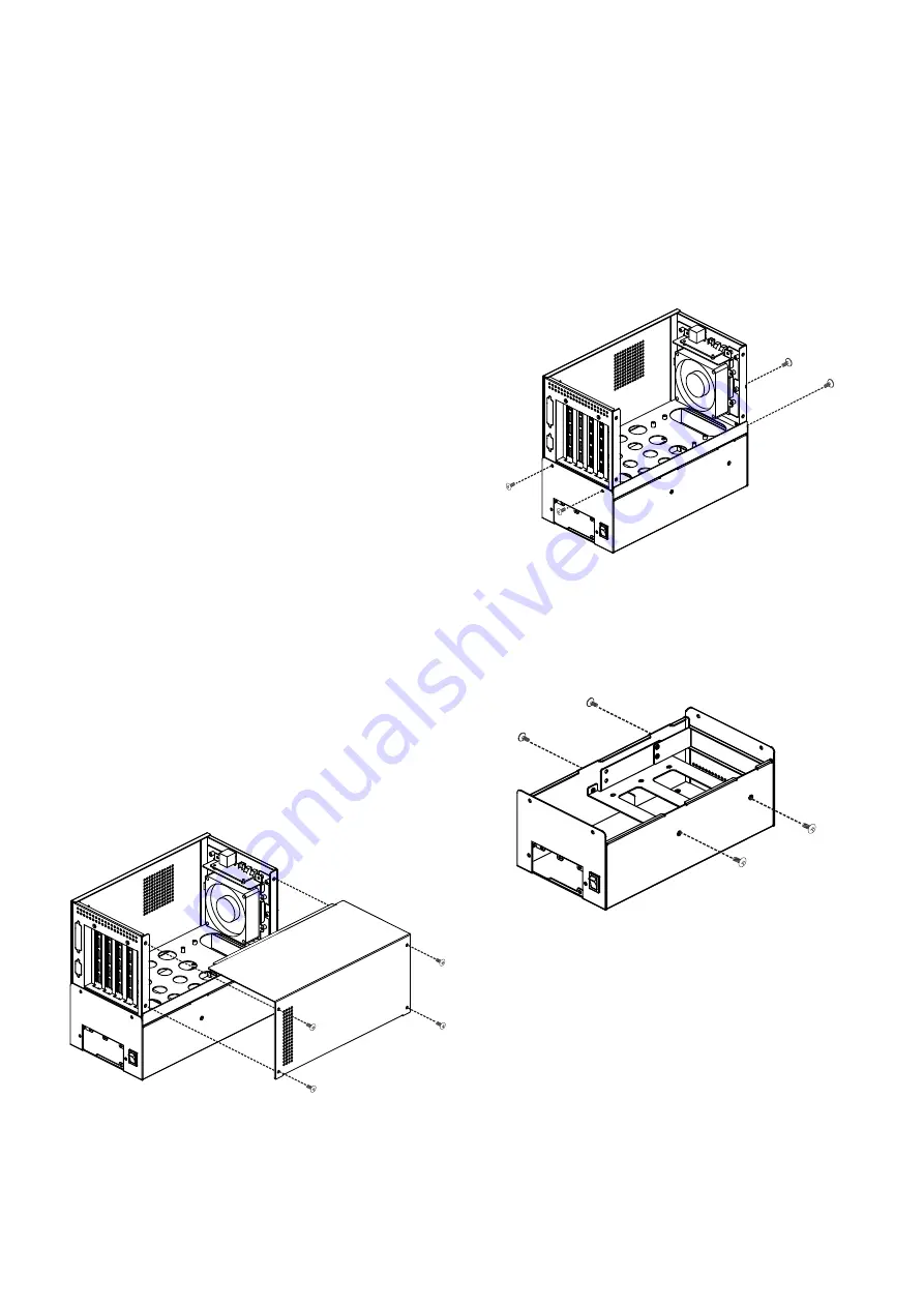
STEP 2: REMOVE THE TOP COVER
The top cover is secured to the chassis with four retention
screws on the left side of the chassis.
Step 1:
Remove all four top cover retention screws from the left
side of the chassis.
Step 2:
Slide the cover leftwards and then lift the cover up gently.
Step 0:
Figure 2: Remove the Top Cover
STEP 3: INSTALL THE POWER SUPPLY
UNIT (PSU)
Once the top cover has been removed, the PSU must be installed.
Compatible 1U IEI PSUs are listed in
Table 2
on
page 4
.
The PSU is secured to the rear of the lower compartment on a PSU
bracket. To install a compatible PSU, please follow the steps below:
Step 1:
Remove the upper compartment by removing the
four upper compartment retention screws, two from
the front and two from the rear of the chassis.
Figure 3: Upper Compartment Retention Screws
Step 2:
Remove the 3.5" drive bracket by removing the four
retention screws from both sides of the drive bracket,
two from each side.
Figure 4: 3.5" HDD Bracket Retention Screws
Step 3:
Remove the PSU bracket located in the lower
compartment by removing the four PSU bracket
retention screws, three from the rear of the chassis
and one from the bottom surface of the chassis.


