


PAC-400AI QIG
IEI Integration Corp.
4
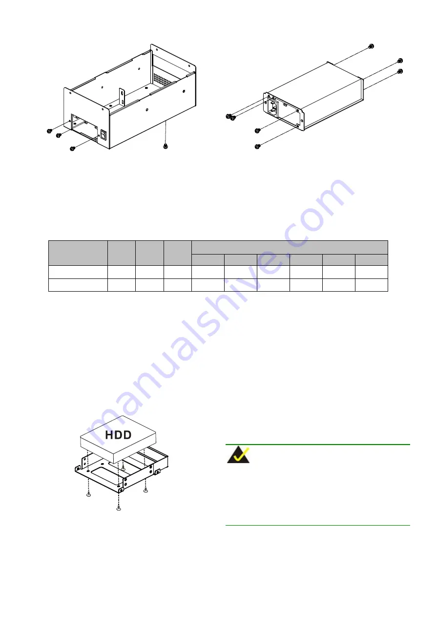
Figure 5: PSU Bracket Retention Screws
Step 4:
Mount the PSU onto the PSU bracket. Make sure the
power socket and the PSU fan are inserted into the
corresponding holes in the rear of the PSU bracket.
Step 5:
To secure the PSU to the PSU bracket, insert seven
retention screws, three into the rear and four into the
front of the PSU bracket.
Figure 6: PSU Retention Screws at the Rear
Step 6:
Reinstall the PSU bracket with the PSU.
Step 7:
To secure the PSU bracket to the chassis, reinsert
the four previously removed PSU bracket retention
screws.
Step 0:
Model No.
Input
Type
Watt
Output Range
+3.3V
+5V
+12V
-5V
-12V
+5Vsb
ACE-916AP-RS
AC
AT
150W
N/A
16A
6A
N/A
0.3A
N/A
ACE-A618B-RS
AC
ATX
180W
10A
14A
10A
N/A
0.3A
2.5A
Table 2: Compatible IEI PSUs
STEP 4: HDD INSTALLATION
The PAC-400AI chassis can support one 3.5" HDD in the lower
compartment. To install a 3.5" HDD, please follow the steps below:
Step 1:
Mount a 3.5" HDD onto the 3.5" drive bracket.
Step 2:
To secure the 3.5" HDD to the 3.5" HDD bracket, insert
four retention screws from the bottom surface of the 3.5"
HDD bracket.
Figure 7: 3.5" HDD Retention Screws
Step 3:
Reinstall the 3.5" drive bracket and reinsert the four
previously removed retention screws.
Step 4:
Connect the 3.5" HDD power connector and SATA
connector.
STEP 5: UPPER COMPARTMENT
REINSTALLATION
Before any other peripherals and components are installed, the
upper compartment must be reinstalled. To do this, please follow the
steps below:
NOTE:
If an AT PSU is installed, the power switch cable must be
connected to the power switch before the upper compartment is
reinstalled.
If an ATX PSU is installed, the power switch cable must be run
through the elliptical hole at the front of the upper compartment
base.
Step 1:
Run all the cables, apart from the AT PSU power switch
cable, through the elliptical hole in the upper compartment
base.


