


PAC-400AI QIG
IEI Integration Corp.
5
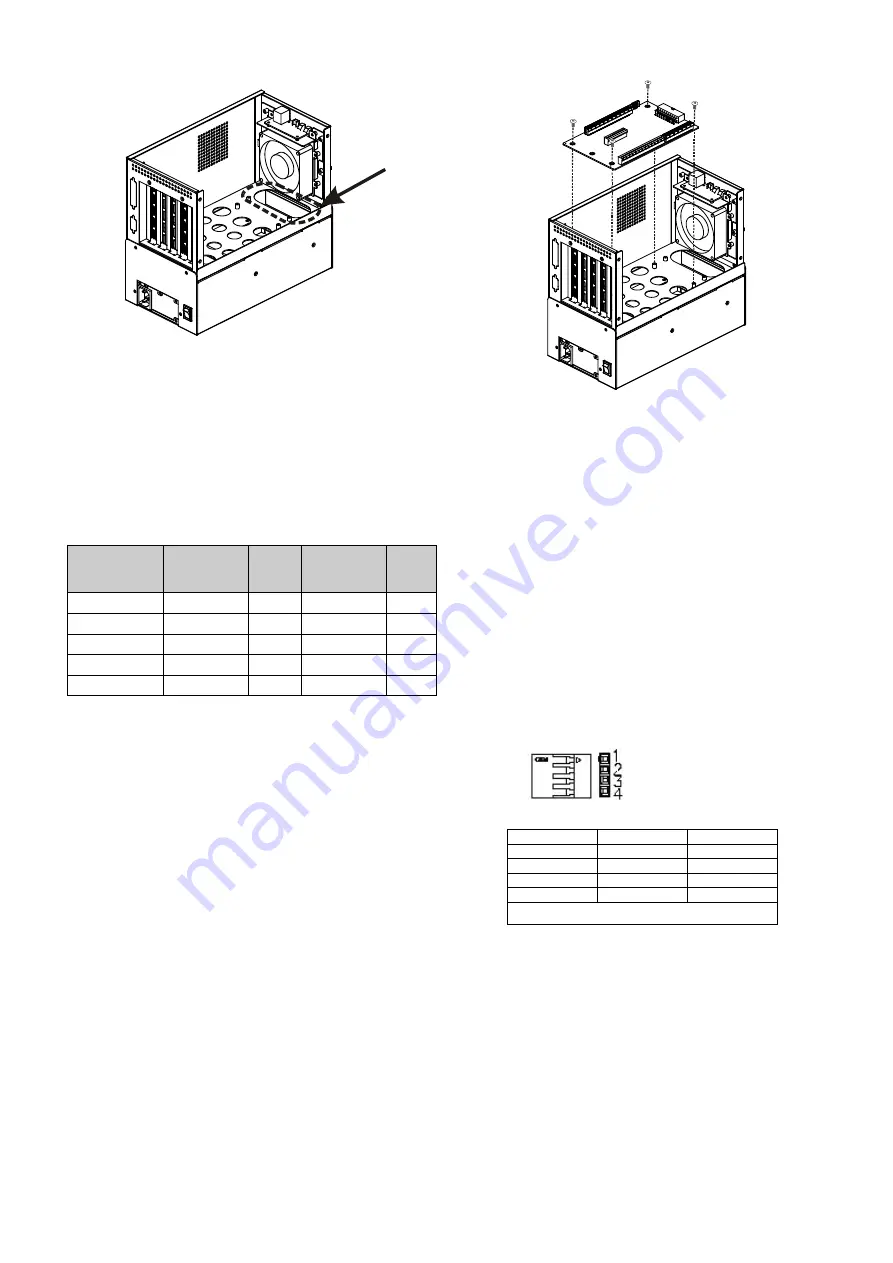
Figure 8: Run the Cables through the Elliptical Hole
Step 2:
Reinstall the upper compartment and reinsert the
four previously removed upper compartment
retention screws.
STEP 6: BACKPLANE INSTALLATION
The compatible IEI backplanes are listed below:
Model No.
SBC Type
PCI
ISA/
PCIe
PSU
BP-4S-RS
ISA
0
4 x ISA
AT
IP-4S-RS
PCISA
3
0
AT
IP-4S2A-RS
PCISA
3
0
ATX
HPE-4S1
PCI/PICOe
3
0
ATX
HPE-4S2
PCI/PICOe
2
1 x PCIe x4 ATX
To install a compatible IEI backplane, please follow the instructions
below:
Step 1:
Mount the backplane onto the base of the upper
compartment. Make sure the backplane is positioned
correctly, so that when the CPU card and PCI/ISA
expansion cards are installed, both the CPU card and
the PCI/ISA card I/O connectors face the rear of the
chassis.
Step 2:
Align the retention screw holes in the backplane with
the retention screw holes in the four elevated predrilled
retention screw holes in the base of the upper
compartment.
Step 3:
Insert four retention screws to secure the backplane to
the chassis.
Figure 9: Elevated Predrilled Screw Holes
Step 4:
Connect the power cable to the backplane.
STEP 7: CABLING
The PAC-400AI has LEDs, buttons and ports on the front
panel and a power switch at the rear panel:
o 1 x Power LED
o 1 x HDD LED
o 1 x Power switch
o 1 x Reset button
o 2 x USB ports
These components are all connected to the CPU card with
cables. To correctly connect these cables, please refer to
the technical documentation that came with your CPU card.
USB cable pin definitions are shown below
PIN No.
Description
Color
1
+5V
Red
2
D-
Dark Yellow
3
D+
Yellow
4
GND
Brown
Table 3: USB Cable Pinouts


