


PAC-400AI QIG
IEI Integration Corp.
6
STEP 8: CPU CARD INSTALLATION
To install a CPU card, please follow the instructions below:
NOTE:
The cables must be connected to the CPU card before the CPU
card installation due to the limitation of the space.
Step 1:
Connect the HDD, USB, LED, reset and power cables to
the CPU card.
Step 2:
Remove the slot cover at the back of the chassis. To do
this, remove the slot cover retention screw at the top of
the slot cover.
Step 3:
Slide the half-size CPU card into the socket on the
backplane reserved for the CPU card. Make sure the back
edge of the CPU card slots into the corresponding card
guide located at the front of the chassis.
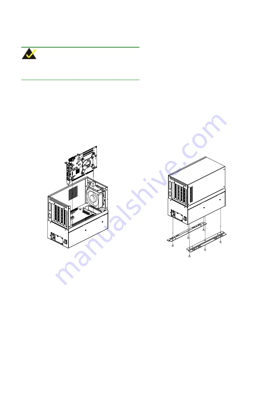
Figure 10: Slide the CPU Card into the Socket
Step 4:
To secure the CPU card, reinsert the previously removed
slot cover retention screw.
Step 0:
STEP 9: PCI/ISA EXPANSION CARD
INSTALLATION
The PAC-400AI supports up to four PCI/ISA expansion
cards. If you wish to install a PCI expansion card or an ISA
expansion card please follow the instructions below:
Step 1:
Remove the slot cover at the back of the chassis. To do
this, remove the slot cover retention screw at the top of
the slot cover.
Step 2:
Slide the PCI/ISA expansion card into the reserved
PCI/ISA socket on the backplane.
Step 3:
To secure the PCI/ISA expansion card, reinsert the
previously removed slot cover retention screw.
Step 0:
STEP 10: TOP COVER REINSTALLATION
After you have completed the above procedures, the top cover can
be reinstalled.
To reinstall the top cover, slide the cover back over
the chassis and reinsert the four previously removed retention
screws.
STEP 11: WALL-MOUNT PLATES
INSTALLATION
Two wall-mount plates are shipped with the PAC-400AI chassis. The
wall-mount plates are installed on the sides, at the bottom of the
chassis. Each plate is secured to the chassis with three retention
screws. To install the wall-mount plates, please follow the steps
below:
Step 1:
Align the retention screw holes on the side of the chassis
with the retention screw holes in the wall-mount plate.
Step 2:
Insert three retention screws into each wall-mount plate.
Step 0:
Figure 11: Wall-mount Plate Retention Screws


