5
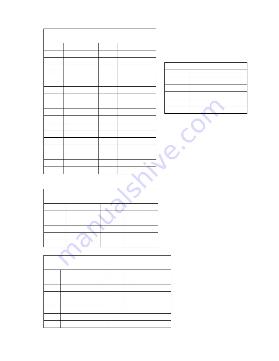
USB1,2,3:
s US
onnec
2 port
B C
tor
Pin No. De
on
scripti
P
o.
in N
D
n
escriptio
1 VCC 2 GND
3 D
-
ATA#
4 DATA#+
5 D
+
ATA#
6 DATA#-
7 GND 8 VCC
FDD1 : Floppy Connector
(2 x 17 pin;
2.54mm pitch)
PIN Description
PIN
Description
1 GND 2 EWC0
3 GND 4 NC
5 NC 6 NC
7 GND 8 INDEX-
9 GND 10 MO-A
11 GND 12 DS-B
13 GND 14 DS-A
15 GND 16 MO-B
17 GND 18 DIR-
19 GND 20 STEP-
21 GND 22 WD-
23 GND 24
WGATE-
25 GND 26 TRK0-
27 GND 28 WP-
31 GND 32 HEAD-
29 GND 30
RDATA-
33 GND 34
DSKCHG-
F_PANEL1: Front Panel Jumper
(2 x 7 pin;
2.54mm pitch)
Pin Description Pin
Description
1 Power
LED+ 2
3 NC 4 NC
5 Power
LED- 6
NC
7 Power
8
Speaker-
9 Power
Button-
10
NC
11
IDE LED+
12
Reset
13
IDE LED-
14
Reset Button-
DIO1: Digital I/O Connector
(2x5
pin;2.54mm pitch)
Pin No Description Pin No Description
1 GND 2 +5V
3 OUTPUT3
4 OUTPUT2
5 OUTPOT1
6 OUTPUT0
7 INPUT3 8 INPUT2
9 INPUT1 10 INPUT0
KB1: Keyboard Connector
Pin No.
Description
1 L_KCLK
2 L_KDAT
3 NC
4 GROUND
5 +5V
Summary of Contents for PCIE-690S1
Page 8: ...Board Layout Jumper and Connector Locations 8...
Page 9: ...9...


