PCIE-Q57A PICMG 1.3 CPU Card
Page 37
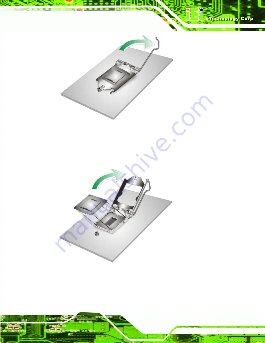
Figure 4-1: Disengage the CPU Socket Load Lever
Step 2:
Open the socket and remove the protective cover.
The black protective
cover can be removed by pulling up on the tab labeled "Remove". See
.
Figure 4-2: Remove Protective Cover
Step 3:
Inspect the CPU socket.
Make sure there are no bent pins and make sure the
socket contacts are free of foreign material. If any debris is found, remove it with
compressed air.
Summary of Contents for PCIE-Q57A
Page 13: ...PCIE Q57A PICMG 1 3 CPU Card Page 1 1 Introduction Chapter 1 ...
Page 21: ...PCIE Q57A PICMG 1 3 CPU Card Page 9 2 Unpacking Chapter 2 ...
Page 25: ...PCIE Q57A PICMG 1 3 CPU Card Page 13 3 Connectors Chapter 3 ...
Page 44: ...PCIE Q57A PICMG 1 3 CPU Card Page 32 4 Installation Chapter 4 ...
Page 66: ...PCIE Q57A PICMG 1 3 CPU Card Page 54 5 BIOS Screens Chapter 5 ...
Page 111: ...PCIE Q57A PICMG 1 3 CPU Card Page 99 Appendix A A Intel AMT Configuration ...
Page 116: ...PCIE Q57A PICMG 1 3 CPU Card Page 104 Appendix B B BIOS Menu Options ...
Page 120: ...PCIE Q57A PICMG 1 3 CPU Card Page 108 Appendix C C One Key Recovery ...
Page 148: ...PCIE Q57A PICMG 1 3 CPU Card Page 136 Appendix D D Terminology ...
Page 153: ...PCIE Q57A PICMG 1 3 CPU Card Page 141 Appendix E E Watchdog Timer ...
Page 156: ...PCIE Q57A PICMG 1 3 CPU Card Page 144 Appendix F F Hazardous Materials Disclosure ...


