background image


Page 130 


IEI® Technology, Corp

.


PICOe-6612 


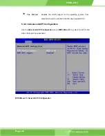
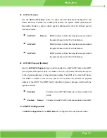
PS/2 Mouse Support [Enabled] 

Use the 

PS/2 Mouse Support

 option adjusts PS/2 mouse support capabilities. 


Disabled 


PS/2 mouse support is disabled and prevented from 

using system resources. 


Enabled D

EFAULT


Allows the system to use a PS/2 mouse. 


Auto 


The system auto-adjusts PS/2 mouse support. 


Wait For ‘F1’ If Error [Enabled] 

Use the 

Wait For ‘F1’ if Error

 option to specify how the system responds when the 

system detects an error on boot up. 


Disabled 


If there is an error when booting up, the system does not 

wait for user intervention but continues to boot up in the 

operating system. Only use this setting if there is a 

known reason for a BIOS error to appear. An example 

would be a system administrator must remote boot the 

system. The computer system does not have a keyboard 

currently attached. 


Enabled D

EFAULT


If there is an error during boot up, the system waits for a 

user to press “F1” and enter the BIOS to rectify the 

problem. The BIOS can then be adjusted to the correct 

settings. 


Hit ‘DEL’ Message Display [Enabled] 

Use the 

Hit “DEL” Message Display

 option to specify whether the instruction to hit the 

delete button to enter BIOS during POST appears or not. 


Disabled 


No message displayed during POST 

Summary of Contents for PICOe-6612 Series

Page 1: ...0 1 PICOe 6612 1...

Page 2: ...inability to use the product or documentation even if advised of the possibility of such damages This document contains proprietary information protected by copyright All rights are reserved No part...

Page 3: ...3 BOARD DIMENSIONS 24 2 4 CPU SUPPORT 24 2 4 1 Pentium M 25 2 4 2 Celeron M 25 2 5 ONBOARD CHIPSETS 26 2 5 1 Northbridge and Southbridge Chipsets 26 2 5 2 SiS661CX Northbridge Chipset 26 2 5 3 SiS966...

Page 4: ...2 INTERNAL PERIPHERAL CONNECTORS 41 3 2 1 Audio Connector 9 pin 42 3 2 2 Backplane to Mainboard Connector 43 3 2 3 CompactFlash Connector 44 3 2 4 Digital Input Output DIO Connector 45 3 2 5 Fan Conn...

Page 5: ...3 2 DIMM Module Installation 77 4 5 JUMPER SETTINGS 78 4 5 1 Clear CMOS Jumper 79 4 5 2 LVDS Voltage Selection 81 4 5 3 LVDS Voltage Selection 82 4 6 CHASSIS INSTALLATION 83 4 6 1 Chassis selection 8...

Page 6: ...5 5 3 6 1 Advanced ACPI Configuration 116 5 3 7 MPS Configuration 117 5 3 8 USB Configuration 119 5 4 PCI PNP 121 5 5 BOOT 127 5 5 1 Boot Settings Configuration 128 5 5 2 Boot Device Priority 131 5 5...

Page 7: ...IGNMENTS 187 D EXTERNALAC 97 AUDIO CODEC 189 D 1 1 Accessing the AC 97 Codec 190 D 1 2 Driver Installation 190 D 2 SOUND EFFECT CONFIGURATION 190 D 2 1 Accessing the Sound Effects Manager 190 D 2 2 So...

Page 8: ...mary IDE Device Connector Locations 51 Figure 3 11 IR Connector Pinout Locations 53 Figure 3 12 Keyboard Connector Location 54 Figure 3 13 LVDS Connector Locations 56 Figure 3 14 Panel Backlight Conne...

Page 9: ...Screen 152 Figure 6 5 Restart the Computer 153 Figure 6 6 InstallShield Wizard Extracting Files 154 Figure 6 7 Audio Driver Install Shield Wizard Starting 154 Figure 6 8 Audio Driver Setup Preparatio...

Page 10: ...ll 168 Figure 6 28 Setup Status 169 Figure 6 29 Restart the Computer 170 Figure 6 30 Starting Install Shield Wizard 171 Figure 6 31 Preparing Setup 171 Figure 6 32 VGA Utilities Welcome Screen 172 Fig...

Page 11: ...e 3 7 DIO Connector Connector Pinouts 46 Table 3 8 Fan Connector Pinouts 47 Table 3 9 FDD Connector Pinouts 49 Table 3 10 Front Panel Connector Pinouts 50 Table 3 11 Primary IDE Connector Pinouts 52 T...

Page 12: ...nouts 67 Table 4 1 Jumpers 79 Table 4 2 Clear CMOS Jumper Settings 80 Table 4 3 LVDS Voltage Selection Jumper Settings 81 Table 4 4 LVDS Voltage Selection Jumper Settings 83 Table 4 5 IEI Provided Cab...

Page 13: ...nu 9 ACPI Configuration 115 BIOS Menu 10 General ACPI Configuration 116 BIOS Menu 11 MPS Configuration 118 BIOS Menu 12 USB Configuration 119 BIOS Menu 13 PCI PnP Configuration 122 BIOS Menu 14 Boot 1...

Page 14: ...FIO Flexible File Input Output FIFO First In First Out FSB Front Side Bus IrDA Infrared Data Association HDD Hard Disk Drive IDE Integrated Data Electronics I O Input Output ICH4 I O Controller Hub 4...

Page 15: ...Page 15 PICOe 6612 1 Chapter 1 Introduction...

Page 16: ...odels The PICOe 6612 series has four models PICOe 6612 R10 PICOe 6612LVDS R10 The specifications for the two models are show in Table 1 1 PICOe 6612 R10 LVDS R10 CRT LCD YES YES Dual GbE YES YES Dual...

Page 17: ...CIe x 1 expansion boards supported Front side bus FSB up to 533MHz supported Up to 1GB of 400MHz DDR memory supported Dual channel 24 bit LVDS supported Two high performance gigabit Ethernet GbE contr...

Page 18: ...d connector 1 x CompactFlash connector 1 x Digital input output DIO connector 1 x Fan connector 1 x Floppy disk drive connector 1 x Front panel connector 1 x IDE connector 1 x Infrared connector 1 x K...

Page 19: ...Oe 6612 technical specifications are listed in Table 1 2 Detailed descriptions of each specification can be found in Chapter 2 Detailed Specifications Specification PICOe 6612 Form Factor Half size CP...

Page 20: ...cts to two Ultra ATA33 66 100 devices Parallel Port One LPT port connector SATA Four 150Mb s SATA connectors KB MS One PS 2 connector and one onboard connector WDT Software programmable 1 255 sec by s...

Page 21: ...Page 21 PICOe 6612 Dimensions 165mm x 115mm Weight GW 1Kg Table 1 2 Technical Specifications...

Page 22: ...Page 22 IEI Technology Corp PICOe 6612 THIS PAGE IS INTENTIONALLY LEFT BLANK...

Page 23: ...Page 23 PICOe 6612 2 Chapter 2 Detailed Specifications...

Page 24: ...g IEI PICMG 1 0 half size HPE backplanes HPE 3S1 HPE 3S2 HPE 4S1 HPE 4S2 HPE 5S1 HPE 5S2 HPE 5S3 HPE 6S1 HPE 6S2 HPE 7S1 HPE 8S0 For more details about these backplanes please refer to the IEI website...

Page 25: ...e Positioning Intel MVP IV dynamically lowers voltage based on processor activity to lower thermal design power Micro FCPGA FCBGA packaging technology optimized for a range of thinner lighter designs...

Page 26: ...rating system Table 2 3 lists the Intel Celeron M processors supported by the PICOe 6612 motherboard Processor Number Power Architecture L2 Cache Speed FSB Execute Disable Bit 370 Normal 90nm 1MB 1 50...

Page 27: ...ipset The SiS966 southbridge chipset comes with the following features SiS MuTIOL 1G Delivering 1GB s Bandwidth o Proprietary Interconnect between SiS north bridge and SiS966 southbridge o Bi Directio...

Page 28: ...ant Dual IDE Channels with ATA 133 100 Support Up to 6 PCI Masters LPC 1 1 Interface Integrated Keyboard PS2 Mouse Controller 2 6 Data Flow Figure 2 1 shows the data flow between the two onboard chips...

Page 29: ...3 2GB s with DDR400 Advanced Hardware Acceleration for DVD playback Dual 12 bit DDR Digital Interface for Digital LCD TV OUT support o NTSC PAL TV OUT o LCD Monitor o Dual view function support for L...

Page 30: ...o Negotiation with Next page capability Supports PCI 2 3 32bit 33 66MHz Supports pair swap polarity skew correction Crossover Detection Auto Correction Wake on LAN and remote wake up support Microsoft...

Page 31: ...ICOe 6612 supports a single FDD The following FDD formats are compatible with the board 5 25 360KB and 1 2MB 3 5 720KB 1 44MB and 2 88MB 2 11 3 CompactFlash Support Standard CF Type 2 cards can be ins...

Page 32: ...n external USB port connector supports the fifth USB 2 0 or USB 1 1 device 2 16 BIOS The PICOe 6612 uses a licensed copy of AMI BIOS The features of the flash BIOS used are listed below SMIBIOS DMI co...

Page 33: ...sing 14 318MHz 24 576MHz PLL to eliminate crystal 12 288MHz BITCLK input Integrated PCBEEP generator to save buzzer Interrupt capability Three analog line level stereo inputs with 5 bit volume control...

Page 34: ...er Consumption Table 2 4 shows the power consumption parameters for the PICOe 6612 when a 2 13GHz Pentium M processor with a 2MB L2 cache and 533MHz FSB is running with a 1GB DDR400 module Voltage Cur...

Page 35: ...ity CD 1 x Quick Installation Guide 2 20 2 Optional Accessory Items The items shown in the list below are optional accessory items are purchased separately USB cable 5 1 channel audio kit with Realtek...

Page 36: ...Page 36 IEI Technology Corp PICOe 6612 THIS PAGE IS INTENTIONALLY LEFT BLANK...

Page 37: ...Page 37 PICOe 6612 3 Connectors and Jumpers Chapter 3...

Page 38: ...ipheral interface connector locations Section 3 1 2 lists all the peripheral interface connectors seen in Section 3 1 1 3 1 1 PICOe 6612 Layout Figure 3 1 shows the onboard peripheral connectors exter...

Page 39: ...tor and Jumper Locations Solder Side 3 1 2 Peripheral Interface Connectors Table 3 1 shows a list of the peripheral interface connectors on the PICOe 6612 Detailed descriptions of these connectors can...

Page 40: ...ce connector 6 pin header IR1 Keyboard connector 5 pin wafer KB1 LVDS output connector 30 pin crimp LVDS1 Parallel port connector 26 pin box header LPT1 Serial port connector 10 pin box header COM1 Se...

Page 41: ...female VGA1 Table 3 2 Rear Panel Connectors 3 1 4 Onboard Jumpers Table 3 3 lists the onboard jumpers Detailed descriptions of these jumpers can be found in Section 3 3 1 on page 63 Description Label...

Page 42: ...outs See Table 3 4 The audio connector is connected to an onboard codec An external audio connector kit can be connected to the connector to provide sound input and output Figure 3 3 Audio Connector L...

Page 43: ...5 The Backplane to Mainboard connector closes the circuit between the mainboard and the backplane in which it is installed The backplane should have an ATX connector and be powered by an ATX power su...

Page 44: ...Type 50 pin socket 2x25 CN Location See Figure 3 5 CN Pinouts See Table 3 6 A CompactFlash memory module is inserted to the CompactFlash on the solder side of the PCB Figure 3 5 CompactFlash Connecto...

Page 45: ...38 VCC_COM 14 N C 39 CSEL 15 N C 40 N C 16 N C 41 HDD_RESET 17 N C 42 IORDY 18 SA2 43 SDREQ 19 SA1 44 SDACK 20 SA0 45 HDD_ACTIVE 21 DATA 0 46 66DET 22 DATA 1 47 DATA 8 23 DATA 2 48 DATA 9 24 N C 49 DA...

Page 46: ...er programmable Figure 3 6 DIO Connector Connector Locations PIN NO DESCRIPTION PIN NO DESCRIPTION 1 GND 2 VCC 3 Output 3 4 Output 2 5 Output 1 6 Output 0 7 Input 3 8 Input 2 9 Input 1 10 Input 0 Tabl...

Page 47: ...connector has a rotation pin to get rotation signals from fans and notify the system so the system BIOS can recognize the fan speed Please note that only specified fans can issue the rotation signals...

Page 48: ...cation See Figure 3 8 CN Pinouts See Table 3 9 The floppy disk connector FDD1 is connected to a floppy disk drive Figure 3 8 FDD Connector Location PIN NO DESCRIPTION PIN NO DESCRIPTION 1 GND 2 DRVDEN...

Page 49: ...SIDE 1 SELECT 33 GND 34 DISK CHANGE Table 3 9 FDD Connector Pinouts 3 2 7 Front Panel Connector CN Label F_PANEL1 CN Type 12 pin header 2x6 CN Location See Figure 3 9 CN Pinouts See Table 3 10 The fr...

Page 50: ...ND 5 5V 6 SYSRST HDD LED 7 HDD LED Reset 8 GND Table 3 10 Front Panel Connector Pinouts 3 2 8 IDE Connector Primary CN Label PIDE1 CN Type 40 pin box header 2x20 CN Location See Figure 3 10 CN Pinouts...

Page 51: ...ION 1 RESET 2 GROUND 3 DATA 7 4 DATA 8 5 DATA 6 6 DATA 9 7 DATA 5 8 DATA 10 9 DATA 4 10 DATA 11 11 DATA 3 12 DATA 12 13 DATA 2 14 DATA 13 15 DATA 1 16 DATA 14 17 DATA 0 18 DATA 15 19 GROUND 20 N C 21...

Page 52: ...9 HDD ACTIVE 40 GROUND Table 3 11 Primary IDE Connector Pinouts 3 2 9 IR Interface Connector 6 pin CN Label IR1 CN Type 6 pin header 1x6 CN Location See Figure 3 11 CN Pinouts See Table 3 12 The integ...

Page 53: ...Page 53 PICOe 6612 Figure 3 11 IR Connector Pinout Locations PIN NO DESCRIPTION 1 5V 2 NC 3 IRRX 4 GND 5 IRTX 6 CIRRX Table 3 12 IR Connector Pinouts...

Page 54: ...in wafer 1x5 CN Location See Figure 3 12 CN Pinouts See Table 3 13 The keyboard connector can be connected to a standard keyboard directly Figure 3 12 Keyboard Connector Location PIN NO DESCRIPTION 1...

Page 55: ...Oe 6612 3 2 11 LCD LVDS Connector CN Label LVDS1 CN Type 30 pin crimp 2x15 CN Location See Figure 3 13 CN Pinouts See Figure 3 13 The LVDS LCD connector LVDS1 connects to a one or dual channel 24 bit...

Page 56: ...DSA_Y0 5 LVDSA_Y1 6 LVDSA_Y1 7 LVDSA_Y2 8 LVDSA_Y2 9 LVDSA_CLK 10 LVDSA_CLK 11 LVDSA_Y3 12 LVDSA_Y3 13 GND 14 GND 15 LVDSB_Y0 16 LVDSB_Y0 17 LVDSB_Y1 18 LVDSB_Y1 19 LVDSB_Y2 20 LVDSB_Y2 21 LVDSB_CLK 2...

Page 57: ...n wafer 1x5 CN Location See Figure 3 14 CN Pinouts See Table 3 15 The Panel Backlight connector provides the backlight on the LCD panel connected to the PICOe 6612 with 12V of power Figure 3 14 Panel...

Page 58: ...PT1 CN Type 26 pin box header CN Location See Figure 3 15 CN Pinouts See Table 3 16 The PICOe 6612 has one 26 pin header that can be connected to a parallel port connector interface or some other para...

Page 59: ...NTER SELECT LN 18 GROUND 19 GROUND 20 GROUND 21 GROUND 22 GROUND 23 GROUND 24 GROUND 25 GROUND 26 NC Table 3 16 Parallel Port Connector Pinouts 3 2 14 RS 232 Serial Port Connectors CN Label COM1 and C...

Page 60: ......

Page 61: ...A drive connectors CN Location See Figure 3 17 CN Pinouts See Table 3 18 The two SATA drive connectors are connected to two first generation SATA drives First generation SATA drives transfer data at s...

Page 62: ...s CN Label USB01 and USB23 CN Type 8 pin header 2x4 CN Location See Figure 3 18 CN Pinouts See Table 3 19 The two 2x4 USB pin connectors provide connectivity to four additional USB 2 0 ports The USB c...

Page 63: ......

Page 64: ...tor Pinouts 3 3 2 LAN Connectors CN Label LAN1 and LAN2 CN Type RJ 45 CN Location See Figure 3 19 CN Pinouts See Table 3 21 The PICOe 6612 is equipped with two built in GbE Ethernet controllers The co...

Page 65: ...ellow The green LED indicates activity on the port and the yellow LED indicates the port is linked See Table 3 22 STATUS DESCRIPTION STATUS DESCRIPTION GREEN Activity YELLOW Linked Table 3 22 RJ 45 Et...

Page 66: ......

Page 67: ...Page 67 PICOe 6612 7 GROUND 15 DDCCLK 8 GROUND Table 3 24 VGA Connector Pinouts...

Page 68: ...Page 68 IEI Technology Corp PICOe 6612 4 Installation and Configuration Chapter 4...

Page 69: ...d 4 2 Installation Considerations NOTE The following installation notices and installation considerations should be read and understood before the motherboard is installed All installation notices per...

Page 70: ...contact with the PCB circuit connector pins or its components 4 3 Unpacking NOTE If any of the items listed below are missing when the PICOe 6612 is unpacked do not proceed with the installation and...

Page 71: ...cable 1 x Utility CD 1 x Quick installation guide If one or more of these items are missing please contact the reseller or vendor the PICOe 6612 was purchased from and do not proceed any further with...

Page 72: ...board and other electronic components like the CPU and DIMM modules The following components must be installed onto the motherboard or connected to the motherboard during the installation process NOTE...

Page 73: ...an Intel 479 pin CPU onto the motherboard follow the steps below Step 1 Step 2 Is the CPU retention screw in an unlocked position When shipped the retention screw of the CPU socket should be in the u...

Page 74: ...be easily inserted into the socket Insert the CPU To insert the CPU into the socket hold the CPU by its edges and follow the instructions below Correctly orientate the CPU with the IHS Integrated Hea...

Page 75: ...heat sink Thermal paste between the CPU and the heat sink is important for optimum heat dissipation To install the CF 479B RS cooling kit please follow the steps below Step 1 Step 2 Step 3 Place the...

Page 76: ...tighten the four screws Tighten each nut a few turns at a time and do not over tighten the screws Connect the fan cable Connect the cooling kit fan cable to the fan connector on the motherboard Caref...

Page 77: ...Module Installation The PICOe 6612 motherboard has one DDR SDRAM DIMM socket To install the DIMM module follow the instructions below and refer to Figure 4 6 Step 1 Step 2 Step 3 Pull the two white ha...

Page 78: ...is used to close an electrical circuit It consists of two metal pins and a small metal clip often protected by a plastic cover that slides over the pins to connect them To CLOSE SHORT a jumper mean c...

Page 79: ...ee Table 4 2 Jumper Location See Figure 4 7 If the PICOe 6612 fails to boot due to improper BIOS settings use this connector to clear the CMOS data and reset the system BIOS information To do this use...

Page 80: ...PICOe 6612 Clear CMOS DESCRIPTION Short 1 2 Default Keep CMOS Setup Short 2 3 Clear CMOS Setup Table 4 2 Clear CMOS Jumper Settings The location of the clear CMOS jumper is shown in Figure 4 7 below F...

Page 81: ...cam with the monitor to select the correct voltage Jumper Label J_LVDS1 Jumper Type 3 pin header Jumper Settings See Table 4 3 Jumper Location See Figure 4 8 The J_LVDS1 jumper allows the LVDS screen...

Page 82: ...election Jumper Label J_LVDS1 Jumper Type 2 pin header Jumper Settings See Figure 4 9 Jumper Location See Table 4 4 The VCCA Voltage FSB reference voltage can be selected by using J_VCCA1 Use the jump...

Page 83: ...tage Selection Jumper Settings The LVDS Voltage Selection jumper location is shown in Figure 4 9 Figure 4 9 LVDS Voltage Selection Jumper Settings 4 6 Chassis Installation Cables provided by IEI that...

Page 84: ...l a backplane into a chassis Install the CompactFlash card optional Mount the PICOe 6612 onto the backplane Install the RS 232 cable optional Connect the PICOe 6612 to the hard disks optional Connect...

Page 85: ...guides respectively 4 6 3 Install the CompactFlash card To install the a CF card Type 1 or Type 2 onto the PICOe 6612 please follow the steps below Step 1 Step 2 Step 3 Step 4 Place the CPU card on a...

Page 86: ...tion that came with the chassis Connect the CPU card top backplane connector ATXCTL1 to the corresponding connector on the backplane For details refer to the documentation that came with the backplane...

Page 87: ...a dual USB cable The dual USB cable consists of two connectors attached to two independent cables Each cable is then attached to a USB port connector that is mounted on a bracket To install the USB ca...

Page 88: ...ow the instructions below Step 1 Step 2 Step 3 Step 4 Find the ATA 66 100 flat cable in the kit that came with the motherboard Locate the 40 pin IDE connector on the motherboard Connect one of the con...

Page 89: ...ipped with two SATA drive cables and one SATA drive power cable To connect the SATA drives to the connectors please follow the steps below Locate the SATA drive connector on the board Press the clip o...

Page 90: ...A drive Figure 4 14 Figure 4 14 SATA Drive Connection 4 7 Rear Panel Connectors 4 7 1 LCD Panel Connection Connect the VGA connector to a standard monitor 4 7 2 Ethernet Connection The rear panel RJ 4...

Page 91: ...and quicker access to external USB devices The rear panel USB connector is a standard connector and can easily be connected to other USB devices 4 7 4 Keyboard and Mouse Connection A PS 2 keyboard an...

Page 92: ...Page 92 IEI Technology Corp PICOe 6612 THIS PAGE IS INTENTIONALLY LEFT BLANK...

Page 93: ...Page 93 PICOe 6612 5 AMI BIOS Setup Chapter 5...

Page 94: ...een 0 If the message disappears before restart the computer and try again 5 1 2 Using Setup Use the arrow keys to highlight items press ENTER to select use the PageUp and PageDown keys to change entri...

Page 95: ...o the system configuration is made CMOS defaults Use the jumper described in Chapter 4 Section 4 5 1 5 1 5 BIOS Menu Bar The menu bar on top of the BIOS screen has the following main items Main Change...

Page 96: ...Main System Overview The System Overview lists a brief summary of different system components The fields in System Overview cannot be changed The items shown in the system overview include AMI BIOS D...

Page 97: ...anced The Advanced menu BIOS Menu 2 allows access to the CPU and peripheral device configuration options through the following sub menus WARNING Setting the wrong values in the sections below may caus...

Page 98: ...Page 98 IEI Technology Corp PICOe 6612 BIOS Menu 2 Advanced 5 3 1 CPU Configuration The CPU Configuration menu BIOS Menu 3 shows detailed CPU specifications and CPU configuration options...

Page 99: ...String Lists the brand name of the CPU being used Frequency Lists the CPU processing speed FSB Speed Lists the FSB speed Cache L1 Lists the CPU L1 cache size Cache L2 Lists the CPU L2 cache size The...

Page 100: ...Clock Spread Spectrum option to reduce the EMI Excess EMI is generated when the system clock generator pulses have extreme values Spreading the pulse spectrum modulates changes in the extreme values f...

Page 101: ...channels used by the onboard PCI IDE controller The following configuration options are available Disabled Prevents the system from using the onboard IDE controller Primary Only allows the system to...

Page 102: ...DE 2P2S IDE 2S RAID 2P2S IDE 2S AHCI 4P IDE 2S RAID 4P IDE 2S AHCI IDE Master and IDE Slave When entering setup BIOS auto detects the presence of IDE devices This displays the status of the auto detec...

Page 103: ...onds 5 seconds Default 10 seconds 15 seconds 20 seconds 25 seconds 30 seconds 35 seconds The best setting to use if the onboard IDE controllers are set to a specific IDE disk drive in the AMIBIOS is 0...

Page 104: ...used Device The IDE disk drive to detects the type of IDE cable used IDE PIO Pre Fetch Enable Disabled Use the IDE PIO PreFetch Enable Option to enable the IDE controller to pre fetch IDE data Disabl...

Page 105: ...type e g hard disk CD ROM etc Type Indicates the type of devices a user can manually select LBA Mode Indicates whether the LBA Logical Block Addressing is a method of addressing data on a disk drive i...

Page 106: ...to the specified channel This setting should be used if an IDE hard disk drive is attached to the specified channel CD DVD The CD DVD option specifies that an IDE CD ROM drive is attached to the speci...

Page 107: ...supported the data transfer to and from the device occurs multiple sectors at a time PIO Mode Auto Use the PIO Mode option to select the IDE PIO Programmable I O mode program timing cycles between th...

Page 108: ...Technology SMART on the drive on the specified channel S M A R T predicts impending drive failures The S M A R T BIOS option enables or disables this function Auto DEFAULT BIOS auto detects HDD SMART...

Page 109: ...n Floppy A Disabled The Floppy A configuration option determines the types of the floppy drive installed in the system The following configuration options are available Disabled default 360 KB 5 1 2 M...

Page 110: ...n the system The following configuration options are available Disabled default 360 KB 5 1 2 MB 5 720 KB 3 1 44 MB 3 2 88 MB 3 5 3 4 Super IO Configuration The Super IO Configuration menu BIOS Menu 7...

Page 111: ...O port address is 3F8 and the interrupt address is IRQ4 3E8 IRQ4 Serial Port 1 I O port address is 3E8 and the interrupt address is IRQ4 2E8 IRQ3 Serial Port 1 I O port address is 2E8 and the interrup...

Page 112: ...ss is 378 278 Parallel Port I O port address is 278 3BC Parallel Port I O port address is 3BC Parallel Port Mode Normal Use the Parallel Port Mode option to select the mode the parallel port operates...

Page 113: ...an the Normal mode The parallel port is also be compatible with EPP devices described above Parallel Port IRQ IRQ7 Use the Parallel Port IRQ option to set the parallel port interrupt address IRQ5 IRQ5...

Page 114: ...are shown The system parameters that are monitored are System Temperatures The following system temperatures are monitored o Temperature Sensor 1 o System Temperature Fan Speeds The CPU cooling fan s...

Page 115: ...s BIOS Menu 9 ACPI Configuration ACPI Aware O S Yes Use the ACPI Aware O S option to enable the system to configure ACPI power saving options ACPI can only be implemented if the system OS complies wit...

Page 116: ...ort for the operating system This selection should be enabled if the OS does support ACPI 5 3 6 1 Advanced ACPI Configuration Use the Advanced ACPI Configuration menu BIOS Menu 10 to select the ACPI s...

Page 117: ...are provided to the system based on ACPI v3 0 definitions ACPI APIC Support Enabled Use the ACPI APIC Support option to add a pointer to an ACPI APIC table in the RSDT Root System Description Table Th...

Page 118: ...hnology Corp PICOe 6612 BIOS Menu 11 MPS Configuration MPS Revision 1 4 The Multiprocessor Specification MPS for OS specifies the MPS version to be used 1 1 MPS version 1 1 is used 1 4 DEFAULT MPS ver...

Page 119: ...Menu 12 USB Configuration Onboard SiS USB1 1 DEVICE Enabled Use the Onboard SiS USB1 1 DEVICE BIOS option to enable or disable the onboard SiS USB1 1 controller If disabled USB1 1 devices cannot be u...

Page 120: ...drivers loaded When this option is enabled any attached USB mouse or USB keyboard can control the system even when there is no USB driver loaded onto the system Disabled Legacy USB support disabled E...

Page 121: ...ms with OSes that do not support EHCI cannot use the EHCI handoff functionality 5 4 PCI PnP The PCI PnP menu BIOS Menu 12 configures advanced PCI and PnP settings WARNING Setting wrong values for the...

Page 122: ...Page 122 IEI Technology Corp PICOe 6612 BIOS Menu 13 PCI PnP Configuration...

Page 123: ...or the BIOS No DEFAULT If the operating system does not meet the Plug and Play specifications this option allows the BIOS to configure all the devices in the system Yes This setting allows the operati...

Page 124: ...card manufacturer requires palette snooping to be enabled this option should be disabled Enabled PCI devices are informed that an ISA based Graphics device is installed in the system so the ISA based...

Page 125: ...n PCI Slot 2 PCI Slot 3 PCI Slot 3 is selected as the location of the OffBoard PCI IDE adapter card Only select this slot if the adapter card is installed in PCI Slot 3 PCI Slot 4 PCI Slot 4 is select...

Page 126: ...RQ3 IRQ4 IRQ5 IRQ7 IRQ9 IRQ10 IRQ 11 IRQ 14 IRQ 15 DMA Channel Available Use the DMA Channel option to assign a specific DMA channel to a particular PCI PnP device Available DEFAULT The specified DMA...

Page 127: ...y that should be reserved for legacy ISA devices Disabled DEFAULT No memory block reserved for legacy ISA devices 16K 16KB reserved for legacy ISA devices 32K 32KB reserved for legacy ISA devices 64K...

Page 128: ...IOS Menu 14 configures advanced system boot options BIOS Menu 15 Boot Settings Configuration Quick Boot Enabled Use the Quick Boot BIOS option to make the computer speed up the boot process Disabled N...

Page 129: ...rmation during system boot Bootup Num Lock On Use the Bootup Num Lock BIOS option to specify if the number lock setting must be modified during boot up Off Does not enable the keyboard Number Lock aut...

Page 130: ...up the system does not wait for user intervention but continues to boot up in the operating system Only use this setting if there is a known reason for a BIOS error to appear An example would be a sys...

Page 131: ...nal ROMs such as network controllers to trap BIOS interrupt 19 Disabled DEFAULT Does not allow optional ROM to trap interrupt 19 Enabled Allows optional ROM to trap interrupt 19 5 5 2 Boot Device Prio...

Page 132: ...k Drives menu is similar to the Removable Drives BIOS Menu 17 and it specifies the boot sequence of the available HDDs When the menu is opened the HDDs connected to the system are listed as shown belo...

Page 133: ...Removable Drives The Removable Drives menu BIOS Menu 17 specifies the boot sequence of the available FDDs When the menu is opened the FDDs connected to the system are listed as shown below 1st Drive 1...

Page 134: ...similar to the Removable Drives BIOS Menu 17 and it specifies the boot sequence of the available CD DVD drives When the menu is opened the CD drives and DVD drives connected to the system are listed a...

Page 135: ...ence from the available devices is selected If the 1st Drive option is selected a list of available CD DVD drives is shown Select the first CD DVD drive the system boots from If the 1st Drive is not u...

Page 136: ...set or change a user password The default for this option is Not Installed If a user password must be installed select this field and enter the password After the password has been added Install appe...

Page 137: ...Page 137 PICOe 6612 BIOS Menu 19 Chipset 5 7 1 Northbridge SIS661FX Configuration The Northbridge SIS661FX Configuration menu BIOS Menu 19 allows the northbridge chipset to be configured...

Page 138: ...ry Graphics Adapter option to select the graphics adapter the system uses PCI DEFAULT PCI graphics adapter is used AGP AGP graphics adapter is used DRAM CAS Latency 3 Use the CAS Latency Time configur...

Page 139: ...B Default Share Memory Size 32MB Use the Share Memory Size option to set the amount of system memory allocated to the integrated graphics processor when the system boots The system memory allocated ca...

Page 140: ...CD panel resolution Configuration options are listed below 1024 x 768 1280 x 1024 1400 x 1050 1280 x 768 HT x VT 1688 x 806 1600 x 1200 1280 x 768 HT x VT 1408 x 806 TV Display Device Composite Use th...

Page 141: ...verScan to specify whether the overscan or underscan functionalities are enabled on the system Configuration options are listed below UNDERSCAN OVERSCAN Different YPbPrTV Use the Different YPbPrTV to...

Page 142: ...E The OnBoard AC 97 DEVICE option enables or disables the AC 97 CODEC Enabled DEFAULT The onboard AC 97 automatically detected and enabled Disabled The onboard AC 97 is disabled All PCI EXPRESS Contro...

Page 143: ...an ROM Enabled Use the OnBoard Lan ROM option enables or disables the onboard LAN Enabled The onboard LAN device automatically detected and enabled Disabled DEFAULT Onboard LAN device manually disable...

Page 144: ...r Management APM BIOS option allows access to the advanced power management features If this option is disabled the only other option on the screen is the Resume On RTC Alarm Disabled Disables the Adv...

Page 145: ...ller activity Enabled DEFAULT Wake event generated by PCI PME controller activity Restore on AC Power Loss Last State Use the Restore on AC Power Loss option to specify what state the system returns t...

Page 146: ...ailsafe values and to save configuration changes BIOS Menu 23 Exit Save Changes and Exit If configuration changes are complete select this option to save them and exit the BIOS menus Discard Changes a...

Page 147: ...be run select this option Load Optimal Defaults This option loads optimal default values for each of the parameters on the Setup menus F9 key can be used for this operation Load Failsafe Defaults This...

Page 148: ...Page 148 IEI Technology Corp PICOe 6612 THIS PAGE IS INTENTIONALLY LEFT BLANK...

Page 149: ...Page 149 PICOe 6612 6 Chapter 6 Software Drivers...

Page 150: ...k LAN Driver SiS RAID Driver SiS VGA Driver All six drivers can be found on the CD that came with the motherboard To install the drivers please follow the instructions below 6 2 SiS AGP Driver Install...

Page 151: ...6 1 Starting Install Shield Wizard Screen Step 8 Step 9 The Preparing Setup window appears next Figure 6 2 Figure 6 2 Preparing Setup Screen The InstallShield window appears Figure 6 3 Click NEXT to...

Page 152: ...Page 152 IEI Technology Corp PICOe 6612 Figure 6 3 Install Shield Screen Step 10 The installation shield starts to extract and install files Figure 6 4 Figure 6 4 Installing Screen...

Page 153: ...effect the computer must be restarted Click FINISH to restart the computer Step 0 6 3 RealTek Audio Driver ALC655 Installation To install the Realtek Audio driver please follow the steps below Insert...

Page 154: ...InstallShield Wizard Extracting Files Step 2 Step 3 The Realtek AC 97 Audio Setup prepares the InstallShield Wizard Figure 6 7 Figure 6 7 Audio Driver Install Shield Wizard Starting The Setup Status s...

Page 155: ...Page 155 PICOe 6612 Figure 6 8 Audio Driver Setup Preparation Step 4 At this stage the Digital Signal Not Found screen appears Figure 6 9 Click YES to continue Figure 6 9 Audio Driver Digital Signal...

Page 156: ...lation Continues After the driver installation process is complete a confirmation screen appears Figure 6 11 Figure 6 11 Audio Driver Installation Complete The confirmation screen offers the option of...

Page 157: ...ctory where X is the system CD drive and is the appropriate motherboard model number and double click the setup exe installation file to initiate the installation The Choose Setup Language screen appe...

Page 158: ...ect Components screen appears Figure 6 14 Select the appropriate component and click NEXT to continue the installation Figure 6 14 Chipset Driver Readme File Information The driver installation begins...

Page 159: ...he Realtek LAN driver please follow the steps below Step 1 Step 2 Insert the Utility CD that came with the motherboard into the system CD drive Open the X LAN RTL81698169S B 8110S B directory where X...

Page 160: ...Page 160 IEI Technology Corp PICOe 6612 Figure 6 17 Realtek LAN Driver Welcome Click NEXT and the Ready to Install screen appears Figure 6 18 Step 3...

Page 161: ...ady to Install Click INSTALL and the Setup Status screen appears as the driver is installed Figure 6 19 Step 4 Step 5 Figure 6 19 Realtek LAN Driver Setup Status After the driver installation process...

Page 162: ...n To install the SiS RAID driver please follow the steps below Insert the Utility CD that came with the motherboard into the system CD drive Open the X RAID V304c directory where X is the system CD dr...

Page 163: ...Page 163 PICOe 6612 Step 3 Step 4 The Preparing Setup window appears next Figure 6 22 Figure 6 22 Preparing Setup The InstallShield window appears next Figure 6 23...

Page 164: ...Page 164 IEI Technology Corp PICOe 6612 Figure 6 23 Install Shield Click NEXT and a License Agreement screen appears Figure 6 24 Read the license agreement Step 5...

Page 165: ...Page 165 PICOe 6612 Figure 6 24 License Agreement Step 6 To accept the terms and conditions stipulated in the license agreement click NEXT...

Page 166: ...6 25 Install Application Directory Step 7 The Install Application Directory window appears Figure 6 25 Click CHANGE to manually select a destination folder for the program or click NEXT to accept the...

Page 167: ...e 167 PICOe 6612 Figure 6 26 Select Needed Components Step 8 The Select Needed Components window appears Figure 6 26 Select the necessary components by clicking the checkboxes and click NEXT to contin...

Page 168: ...68 IEI Technology Corp PICOe 6612 Figure 6 27 Ready to Install Step 9 The Ready to Install window appears Figure 6 27 Click INSTALL and the install shield begins to extract and install the files Figur...

Page 169: ...Page 169 PICOe 6612 Figure 6 28 Setup Status Step 10 After the driver installation process is complete a confirmation screen appears Figure 6 29...

Page 170: ...Click FINISH to restart the computer Step 0 6 7 SiS VGA Utilities Driver To install the SiS VGA Utilities driver please follow the steps below Insert the Utility CD that came with the motherboard int...

Page 171: ...e 171 PICOe 6612 Figure 6 30 Starting Install Shield Wizard Step 3 Step 4 The Preparing Setup window appears next Figure 6 31 Figure 6 31 Preparing Setup The InstallShield window appears next Figure 6...

Page 172: ...Setup Type screen appears Figure 6 33 Select the preferred setup type and click NEXT to continue the installation Figure 6 33 Select Setup Installation Type The Select Program Folder screen appears F...

Page 173: ...ICOe 6612 Figure 6 34 Select Folders to Copy Files Step 7 The Start Copying Files screen appears Figure 6 35 Review the selected settings and click NEXT to continue the installation Figure 6 35 Review...

Page 174: ...installation begins Once the installation is complete the Setup Type screen appears Figure 6 36 Figure 6 36 Read ReadMe File Click NEXT to read the ReadMe file After reading the ReadMe file a confirma...

Page 175: ...PICOe 6612 Step 10 The confirmation screen offers the option of restarting the computer now or later For the settings to take effect the computer must be restarted Click FINISH to restart the compute...

Page 176: ...Page 176 IEI Technology Corp PICOe 6612 THIS PAGE IS INTENTIONALLY LEFT BLANK...

Page 177: ...Page 177 PICOe 6612 A Appendix A BIOS Configuration Options...

Page 178: ...abled 103 IDE Detect Time Out Sec 35 103 ATA PI 80Pin Cable Detection Host Device 103 IDE PIO Pre Fetch Enable Disabled 104 Auto Detected Drive Parameters 105 Type Auto 106 ZIP 106 LS 120 106 LBA Larg...

Page 179: ...mer 64 123 Allocate IRQ to PCI VGA Yes 124 Palette Snooping Disabled 124 PCI IDE BusMaster Disabled 124 OffBoard PCI ISA IDE Card Auto 125 IRQ Available 125 DMA Channel Available 126 Reserved Memory S...

Page 180: ...0 TV NTSC PAL Display NTSC 140 Different PAL TV PAL 141 TV UnderScan OverScan 141 Different YPbPrTV 141 OnBoard Audio DEVICE 142 All PCI EXPRESS Controller Enabled 142 OnBoard Lan ROM Enabled 143 Powe...

Page 181: ...Page 181 PICOe 6612 B Watchdog Timer Appendix B...

Page 182: ...A BIOS function call INT 15H is used to control the Watchdog Timer INT 15H AH 6FH Sub function AL 2 Sets the Watchdog Timer s period BL Time out value Its unit second is dependent on the item Watchdo...

Page 183: ...resets Example program INITIAL TIMER PERIOD COUNTER W_LOOP MOV AX 6F02H setting the time out value MOV BL 30 time out value is 48 seconds INT 15H ADD THE APPLICATION PROGRAM HERE CMP EXIT_AP 1 is the...

Page 184: ...Page 184 IEI Technology Corp PICOe 6612 THIS PAGE IS INTENTIONALLY LEFT BLANK...

Page 185: ...Page 185 PICOe 6612 C Address Mapping Appendix C...

Page 186: ...troller 0F0 0FF Numeric data processor 1F0 1F7 Primary IDE Channel 2F8 2FF Serial Port 2 COM2 378 37F Parallel Printer Port 1 LPT1 3B0 3BB Graphics Controller 3C0 3DF Graphics Controller 3F6 3F6 Prima...

Page 187: ...IRQ4 COM1 IRQ12 PS 2 mouse IRQ5 SMBus Controller IRQ13 FPU IRQ6 FDC IRQ14 Primary IDE IRQ7 Available IRQ15 Secondary IDE Table C 3 IRQ Mapping Table C 4 DMA Channel Assignments Channel Function 0 Ava...

Page 188: ...Page 188 IEI Technology Corp PICOe 6612 THIS PAGE IS INTENTIONALLY LEFT BLANK...

Page 189: ...Page 189 PICOe 6612 D External AC 97 Audio CODEC Appendix D...

Page 190: ...DIO2 An audio 10 pin to phone jack adapter kit is required D 1 2 Driver Installation The driver installation has been described in Section 6 3 After rebooting the sound effect configuration utility ap...

Page 191: ...ound Effect Manager icon in the Notification Area of the system task bar Figure D 2 or The Sound Effect Manager icon in the Control Panel Figure D 3 Figure D 2 Sound Effect Manager Icon Task Bar Figur...

Page 192: ...rent codecs may have different sound manager appearances The following Section describes the different configuration options in the Sound Effect Manager D 2 2 Sound Effect Manager Configuration Option...

Page 193: ...NOTE Not all RealTek Sound Effect Managers have all the above listed options The Sound Effect Manager loaded onto the system may only have some of the options listed above Below is a brief descriptio...

Page 194: ...ut o Channel mode for 5 1 speaker output o Synchronize the phonejack switch with speakers settings Speaker Test Each speaker connected to the system is tested individually to see if the 4 channel or 6...

Page 195: ...Page 195 PICOe 6612 E RAID Setup Appendix E...

Page 196: ...ation on that drive is lost RAID0 refers to disk striping Data is distributed striped over multiple disks This increases the overall disk performance but the data is not redundantly stored and therefo...

Page 197: ...CD that came with the system onto a floppy disk To do this follow the steps below Insert the CD into a computer and navigate to the RAID 304c directory Figure E 1 Figure E 1 RAID 304C Subdirectory Sel...

Page 198: ...ow the steps below Turn on the motherboard and enter the BIOS setup utility Do this by pressing DELETE when the system boots up Select the Advanced Settings menus Select the IDE Configuration sub menu...

Page 199: ...6612 Step 2 Step 3 The system prompts the user to press CTRL and S to enter the BIOS RAID Setup Utility Figure E 4 Figure E 4 BIOS RAID Utility To setup the RAID press R The RAID setup screen will app...

Page 200: ...p PICOe 6612 Figure E 5 Create RAID Step 4 Step 5 Click A to setup the RAID Figure E 5 The system then prompts the user to select the RAID configuration type JBOD RAID0 or RAID1 Select the desired RAI...

Page 201: ...Page 201 PICOe 6612 Figure E 6 Create RAID Step 6 The system then prompts the user to Auto Create or Manual Create Figure E 7...

Page 202: ...Page 202 IEI Technology Corp PICOe 6612 Figure E 7 Select Auto Step 7 The user is prompted to Auto Create or Manual Create Select Auto Create Figure E 8...

Page 203: ...he OS onto the SATA drives To do this follow the steps below Insert the OS installation CD into the CD drive attached to the IDE device Restart the system When prompted press F6 to install the RAID co...

Page 204: ...p 6 Step 7 Next select the driver for the OS being installed into the system Once selected press ENTER The OS and the RAID drivers are then installed into the system The SATA drives are configured as...

Page 205: ...Page 205 PICOe 6612 F Index...

Page 206: ...Page 206 IEI Technology Corp PICOe 6612...

Reviews: