Page 45
POC-3174B-A330 Medical Panel PC
Step 3:
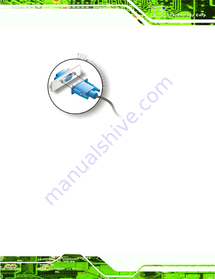
Insert the VGA connector
.
Once the connectors are properly aligned with the
insert the male connector from the VGA screen into the female connector on the
POC-3174B-A330. See
Figure 4-17: VGA Connector
Step 4:
Secure the connector
. Secure the DB-15 VGA connector from the VGA
monitor to the external interface by tightening the two retention screws on either
side of the connector.
Step 0:
Summary of Contents for POC-3174B-A330
Page 1: ...Page I POC 3174B A330 Medical Panel PC POC 3174B A330 Medical Panel PC ...
Page 17: ...Page 1 POC 3174B A330 Medical Panel PC 1 Introduction Chapter 1 ...
Page 26: ...Page 10 POC 3174B A330 Medical Panel PC 2 Specifications Chapter 2 ...
Page 37: ...Page 21 POC 3174B A330 Medical Panel PC Figure 2 14 UPS Battery Mode Switch ...
Page 40: ...Page 24 POC 3174B A330 Medical Panel PC 3 Unpacking Chapter 3 ...
Page 43: ...Page 27 POC 3174B A330 Medical Panel PC 4 Installation Chapter 4 ...
Page 62: ...Page 46 POC 3174B A330 Medical Panel PC 5 System Maintenance Chapter 5 ...
Page 72: ...Page 56 POC 3174B A330 Medical Panel PC 6 AMI BIOS Setup Chapter 6 ...
Page 117: ...Page 101 POC 3174B A330 Medical Panel PC Chapter 7 7 Software Drivers ...
Page 141: ...Page 125 POC 3174B A330 Medical Panel PC 8 Battery Monitoring and Remote Control Chapter 8 ...
Page 156: ...Page 140 POC 3174B A330 Medical Panel PC A System Specifications Appendix A ...
Page 162: ...Page 146 POC 3174B A330 Medical Panel PC B Safety Precautions Appendix B ...
Page 168: ...Page 152 POC 3174B A330 Medical Panel PC C BIOS Configuration Options Appendix C ...
Page 173: ...Page 157 POC 3174B A330 Medical Panel PC D Watchdog Timer Appendix D ...
Page 176: ...Page 160 POC 3174B A330 Medical Panel PC E Hazardous Materials Disclosure Appendix E ...
Page 180: ...Page 164 POC 3174B A330 Medical Panel PC F International Standards Compliance Appendix F ...
Page 183: ...Page 167 POC 3174B A330 Medical Panel PC Index ...


