PPC-37xxA-N26 Panel PC
Page 23
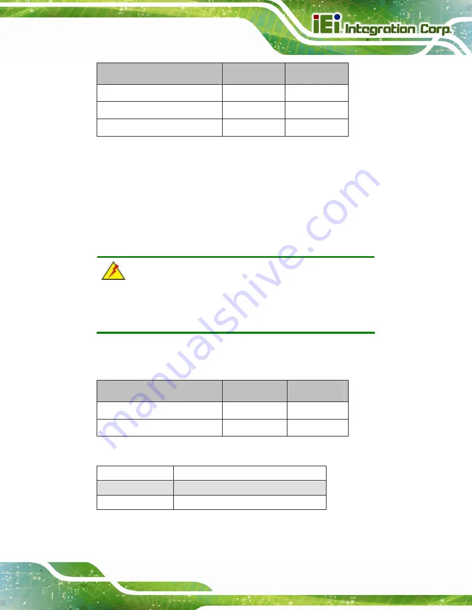
Description
Label
Type
AT/ATX power selection
JP3
2-pin header
Clear CMOS
JP1
3-pin header
mSATA/PCIe Mini mode selection
MSATA_SW1
2-pin header
Table 3-1: Jumpers
3.6.1 Access the Jumpers
To access the jumpers, remove the back cover. To remove the back cover, please refer to
WARNING:
Do not change the settings on the jumpers described here. Doing so
may disable or damage the system
The following jumpers are preconfigured for the PPC-37xxA-N26. Users should not
change these jumpers.
Jumper Name
Label
Type
LVDS voltage selection
JP5
3-pin header
Touchscreen type selection
J_WIRE1
Switch
Table 3-2: Preconfigured Jumpers
Setting
Description
Short 1-2
+3.3V LVDS (Default)
Short 2-3
+5V LVDS
Table 3-3: LVDS Voltage Selection Jumper Settings
Summary of Contents for PPC-37 A-N26 Series
Page 17: ...PPC 37xxA N26 Panel PC Page 1 1 Introduction Chapter 1 ...
Page 29: ...PPC 37xxA N26 Panel PC Page 13 2 Unpacking Chapter 2 ...
Page 34: ...PPC 37xxA N26 Panel PC Page 18 3 Installation Chapter 3 ...
Page 72: ...PPC 37xxA N26 Panel PC Page 56 Chapter 4 4 System Maintenance ...
Page 76: ...PPC 37xxA N26 Panel PC Page 60 5 BIOS Setup Chapter 5 ...
Page 106: ...PPC 37xxA N26 Panel PC Page 90 6 Driver Installation Chapter 6 ...
Page 133: ...PPC 37xxA N26 Panel PC Page 117 7 Interface Connectors Chapter 7 ...
Page 145: ...PPC 37xxA N26 Panel PC Page 129 A BIOS Configuration Options Appendix A ...
Page 148: ...PPC 37xxA N26 Panel PC Page 132 Appendix B B One Key Recovery ...
Page 156: ...PPC 37xxA N26 Panel PC Page 140 Figure B 5 Partition Creation Commands ...
Page 189: ...PPC 37xxA N26 Panel PC Page 173 C Safety Precautions Appendix C ...
Page 194: ...PPC 37xxA N26 Panel PC Page 178 D Watchdog Timer Appendix D ...
Page 197: ...PPC 37xxA N26 Panel PC Page 181 E Hazardous Materials Disclosure Appendix E ...


