PPC-37xxA-N26 Panel PC
Page 50
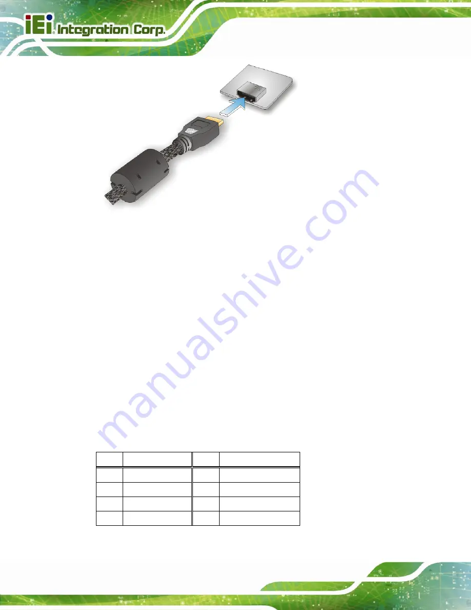
Figure 3-40: HDMI Connection
Step 3:
Insert the HDMI connector
. Gently insert the HDMI connector. The connector
should engage with a gentle push. If the connector does not insert easily, check
again that the connector is aligned correctly, and that the connector is being
inserted with the right way up.
3.11.3 Power Input Connector
The standard system is shipped with a 90 V to 264 V AC power adapter that has a
maximum power output of 60 W. The power adapter has a 12 V DC output connector. The
PPC-37xxA-N26 has one 12 V power input connector on the bottom panel. The location of
the power connector is shown in
.
3.11.4 RJ-45 LAN Connectors
The RJ-45 LAN connectors allow connections to external networks. The pinouts of the
RJ-45 LAN connector is shown below.
Pin Description
Pin Description
1 MDI0+
5 MDI2+
2 MDI0-
6 MDI2-
3 MDI1+
7 MDI3+
4 MDI1-
8 MDI3-
Table 3-8: LAN Pinouts
Summary of Contents for PPC-37 A-N26 Series
Page 17: ...PPC 37xxA N26 Panel PC Page 1 1 Introduction Chapter 1 ...
Page 29: ...PPC 37xxA N26 Panel PC Page 13 2 Unpacking Chapter 2 ...
Page 34: ...PPC 37xxA N26 Panel PC Page 18 3 Installation Chapter 3 ...
Page 72: ...PPC 37xxA N26 Panel PC Page 56 Chapter 4 4 System Maintenance ...
Page 76: ...PPC 37xxA N26 Panel PC Page 60 5 BIOS Setup Chapter 5 ...
Page 106: ...PPC 37xxA N26 Panel PC Page 90 6 Driver Installation Chapter 6 ...
Page 133: ...PPC 37xxA N26 Panel PC Page 117 7 Interface Connectors Chapter 7 ...
Page 145: ...PPC 37xxA N26 Panel PC Page 129 A BIOS Configuration Options Appendix A ...
Page 148: ...PPC 37xxA N26 Panel PC Page 132 Appendix B B One Key Recovery ...
Page 156: ...PPC 37xxA N26 Panel PC Page 140 Figure B 5 Partition Creation Commands ...
Page 189: ...PPC 37xxA N26 Panel PC Page 173 C Safety Precautions Appendix C ...
Page 194: ...PPC 37xxA N26 Panel PC Page 178 D Watchdog Timer Appendix D ...
Page 197: ...PPC 37xxA N26 Panel PC Page 181 E Hazardous Materials Disclosure Appendix E ...


