PPC-37xx-N270 Panel PC
Page 41
Description
Label
Type
AT Power Mode Setting
ATXCTL1
2-pin header
CF Card Setting
JCF1
2-pin header
Clear CMOS
J_CMOS1
3-pin header
COM2 Mode Setting
JP1
6-pin header
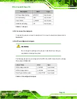
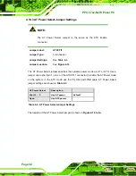
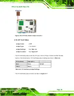
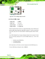
Table 4-1: Jumpers
4.10.1 Access the Jumpers
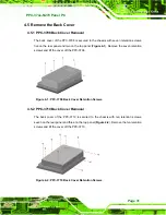
To access the jumpers, remove the back panel. To remove the back panel, please refer to
.
4.10.2 Preconfigured Jumpers
WARNING:
Do not change the settings on the jumpers in described here. Doing so
may disable or damage the system.
The following jumpers are preconfigured for the PPC-37xx-N270. Users should no change
these jumpers (
).
Jumper Name
Label
Type
LVDS voltage selection
J_VLVDS1
3-pin header
LVDS2 Voltage Select
J_VLVDS2
3-pin header
Panel Type and Resolution
J_LCD_TYPE1
8-pin header
Table 4-2: Preconfigured Jumpers
Summary of Contents for PPC-3708A-N270
Page 14: ......
Page 15: ...PPC 37xx N270 Panel PC Page 1 Chapter 1 1 Introduction ...
Page 24: ...PPC 37xx N270 Panel PC Page 10 Chapter 2 2 Detailed Specifications ...
Page 38: ...PPC 37xx N270 Panel PC Page 24 3 Unpacking Chapter 3 ...
Page 42: ...PPC 37xx N270 Panel PC Page 28 4 Installation Chapter 4 ...
Page 77: ...PPC 37xx N270 Panel PC Page 63 5 BIOS Screens Chapter 5 ...
Page 123: ...PPC 37xx N270 Panel PC Page 109 Chapter 6 6 Driver Installation ...
Page 140: ...PPC 37xx N270 Panel PC Page 126 A Safety Precautions Appendix A ...
Page 145: ...PPC 37xx N270 Panel PC Page 131 Appendix B B BIOS Options ...
Page 149: ...PPC 37xx N270 Panel PC Page 135 Appendix C C Watchdog Timer ...
Page 152: ...PPC 37xx N270 Panel PC Page 138 Appendix D D Hazardous Materials Disclosure ...


