


PPC-37xx-N270 Panel PC
Page 59
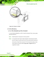
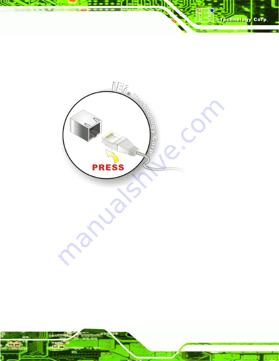
Step 1:
Locate the RJ-45 connectors
on the bottom panel of the PPC-37xx-N270.
Step 2:
Align the connectors.
Align the RJ-45 connector on the LAN cable with one of
the RJ-45 connectors on the bottom panel of the PPC-37xx-N270. See
Figure 4-34: LAN Connection
Step 3:
Insert the LAN cable RJ-45 connector.
Once aligned, gently insert the LAN
cable RJ-45 connector into the onboard RJ-45 connector.
Step 0:
4.12.3 Serial Device Connection
The PPC-37xx-N270 has two single male DB-9 connectors on the bottom panel for a
serial device. Follow the steps below to connect a serial device to the PPC-37xx-N270
panel PC.
Step 1:
Locate the DB-9 connector
. The location of the DB-9 connector is shown in
Chapter 2
.
Step 2:
Insert the serial connector
.
Insert the DB-9 connector of a serial device into
the DB-9 connector on the bottom panel. See
Summary of Contents for PPC-3708A-N270
Page 14: ......
Page 15: ...PPC 37xx N270 Panel PC Page 1 Chapter 1 1 Introduction ...
Page 24: ...PPC 37xx N270 Panel PC Page 10 Chapter 2 2 Detailed Specifications ...
Page 38: ...PPC 37xx N270 Panel PC Page 24 3 Unpacking Chapter 3 ...
Page 42: ...PPC 37xx N270 Panel PC Page 28 4 Installation Chapter 4 ...
Page 77: ...PPC 37xx N270 Panel PC Page 63 5 BIOS Screens Chapter 5 ...
Page 123: ...PPC 37xx N270 Panel PC Page 109 Chapter 6 6 Driver Installation ...
Page 140: ...PPC 37xx N270 Panel PC Page 126 A Safety Precautions Appendix A ...
Page 145: ...PPC 37xx N270 Panel PC Page 131 Appendix B B BIOS Options ...
Page 149: ...PPC 37xx N270 Panel PC Page 135 Appendix C C Watchdog Timer ...
Page 152: ...PPC 37xx N270 Panel PC Page 138 Appendix D D Hazardous Materials Disclosure ...