


PPC-37xx-N270 Panel PC
Page 62
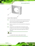
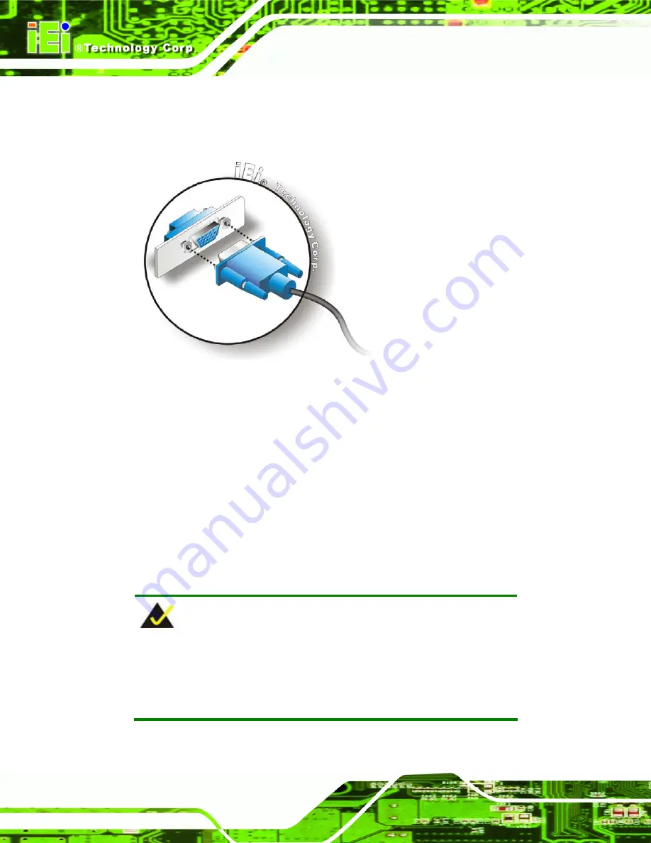
Step 3:
Insert the VGA connector
.
Once the connectors are properly aligned with the
insert the male connector from the VGA screen into the female connector on the
PPC-37xx-N270. See
.
Figure 4-37: VGA Connector
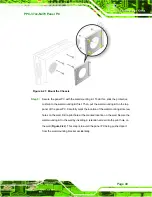
Step 4:
Secure the connector
. Secure the DB-15 VGA connector from the VGA
monitor to the external interface by tightening the two retention screws on either
side of the connector.
S
te
p
0
:
4.13 System Maintenance
If the components of the flat panel PC fail, they must be replaced. Please contact the
system reseller or vendor to purchase the replacement parts. Replacement instructions for
the above listed components are described below.
NOTE:
A user cannot replace a motherboard. If the motherboard fails it must
be shipped back to IEI to be replaced. Please contact the system
vendor, reseller or an IEI sales person directly.
Summary of Contents for PPC-3708A-N270
Page 14: ......
Page 15: ...PPC 37xx N270 Panel PC Page 1 Chapter 1 1 Introduction ...
Page 24: ...PPC 37xx N270 Panel PC Page 10 Chapter 2 2 Detailed Specifications ...
Page 38: ...PPC 37xx N270 Panel PC Page 24 3 Unpacking Chapter 3 ...
Page 42: ...PPC 37xx N270 Panel PC Page 28 4 Installation Chapter 4 ...
Page 77: ...PPC 37xx N270 Panel PC Page 63 5 BIOS Screens Chapter 5 ...
Page 123: ...PPC 37xx N270 Panel PC Page 109 Chapter 6 6 Driver Installation ...
Page 140: ...PPC 37xx N270 Panel PC Page 126 A Safety Precautions Appendix A ...
Page 145: ...PPC 37xx N270 Panel PC Page 131 Appendix B B BIOS Options ...
Page 149: ...PPC 37xx N270 Panel PC Page 135 Appendix C C Watchdog Timer ...
Page 152: ...PPC 37xx N270 Panel PC Page 138 Appendix D D Hazardous Materials Disclosure ...


