PPC-51xxA-H61 Panel PC
Page xiii
Table 6-16: SATA 3Gb/s Connectors (SATA1/SATA2) Pinouts ............................................ 114
Table 6-17: SATA Power Connectors (JSATA_PWR1/JSATA_PWR2 Pinouts .................... 114
Table 6-18: SATA Power Connectors (JSATA_PWR1/JSATA_PWR2 Pinouts .................... 115
Table 6-19: SMBus Connector (SMBUS_1) Pinouts............................................................... 115
Table 6-20: SPI Flash Connector (JSPI1) Pinouts .................................................................. 115
Table 6-21: Touch Panel Connector ( TOUCH1) Pinouts....................................................... 116
Table 6-22: USB 2.0 Connector (USB1/USB2/USB3/USB4) Pinouts..................................... 116
Table 6-23: Rear Panel Connectors ......................................................................................... 117
Table 6-24: RJ-45 LAN Connector Pinouts ............................................................................. 117
Table 6-25: RS-232 Serial Port Pinouts ................................................................................... 117
Table 6-26: RS-232/422/485 Serial Port Pinouts ..................................................................... 118
Table 6-27: USB 2.0 Connectors (USB_CON2) Pinouts......................................................... 118
Table 6-28: USB 3.0 Connectors (USB_CON1) Pinouts......................................................... 119
Table 6-29: VGA Connector (VGA1) Pinouts .......................................................................... 119
Table 6-30: Preconfigured Jumpers ........................................................................................ 120
Table 6-31: CF Card Power Selection Jumper (JP1) Settings............................................... 120
Table 6-32: CPU Fan Type Selection Jumper (JCPUFAN1) Settings ................................... 120
Table 6-33: Inverter Brightness Voltage Selection Jumper (J_ADJ1) Settings .................. 120
Table 6-34: LCD Power Selection Jumper (JLCD_PWR1) Settings...................................... 121
Table 6-35: Panel Type and Resolution Selection Jumper (JLCD_SET1) Settings ............ 121
Table 6-36: Pull High/Low Selection (for RS-422/485 only) Jumper (UART_SEL1) Settings.. 121
Table 6-37: System Fan Type Selection Jumper Settings..................................................... 122
Table 6-38: Touchscreen Selection Jumper (JTOUCH1) Settings........................................ 122
Table 6-39: USB1~USB4 Power Selection Jumpers Settings ............................................... 122
Summary of Contents for PPC-51 A-H61 Series
Page 11: ...PPC 51xxA H61 Panel PC Page xi Figure 6 2 Main Board Layout Diagram Solder Side 106 ...
Page 14: ...PPC 51xxA H61 Panel PC Page 1 1 Introduction Chapter 1 ...
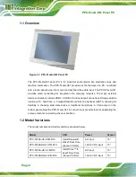
Page 20: ...PPC 51xxA H61 Panel PC Page 7 Figure 1 5 PPC 5150A H61 PPC 5170A H61 Bottom View ...
Page 30: ...PPC 51xxA H61 Panel PC Page 17 2 Unpacking Chapter 2 ...
Page 35: ...PPC 51xxA H61 Panel PC Page 22 3 Installation Chapter 3 ...
Page 49: ...PPC 51xxA H61 Panel PC Page 36 Figure 3 14 Replacing the Optical Drive Bracket ...
Page 75: ...PPC 51xxA H61 Panel PC Page 62 Chapter 4 4 System Maintenance ...
Page 84: ...PPC 51xxA H61 Panel PC Page 71 5 BIOS Setup Chapter 5 ...
Page 117: ...PPC 51xxA H61 Panel PC Page 104 6 Interface Connectors Chapter 6 ...
Page 136: ...PPC 51xxA H61 Panel PC Page 123 Appendix A A Regulatory Compliance ...
Page 141: ...PPC 51xxA H61 Panel PC Page 128 B BIOS Configuration Options Appendix B ...
Page 144: ...PPC 51xxA H61 Panel PC Page 131 C Safety Precautions Appendix C ...
Page 149: ...PPC 51xxA H61 Panel PC Page 136 D Watchdog Timer Appendix D ...
Page 152: ...PPC 51xxA H61 Panel PC Page 139 E Hazardous Materials Disclosure Appendix E ...

