PPC-51xxA-H61 Panel PC
Page 28
Five jumpers configure pin 9 on the COM1, COM2, COM3 COM4 and COM5 connectors.
Pin 9 on these connectors can be set as 5 V, +12 V or as the ring (RI) signal. The
COM1, COM2, COM3, COM4 and COM5 Pin 9 setting jumper selection options are
shown in
6
Table 3-3
.
Short 1 – 3
Short 2 - 4
Serial Port
Default
Default
Short
3 – 5
Short
4 – 6
J_COM_V1
COM1
RI signal
+5 V
Pin 9 power
+12 V
J_COM_V2
COM2
RI signal
+5 V
Pin 9 power
+12 V
J_COM_V3
COM3
RI signal
+5 V
Pin 9 power
+12 V
J_COM_V4
COM4
RI signal
+5 V
Pin 9 power
+12 V
J_COM_V5
COM5
RI signal
+5 V
Pin 9 power
+12 V
Table 3-3: COM1 to COM5 Pin 9 Setting Jumper Settings
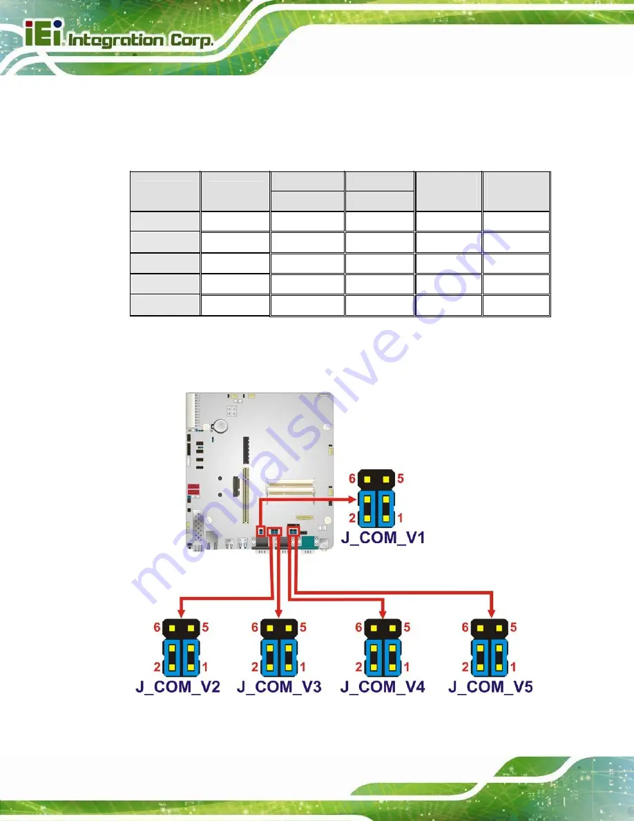
The COM1 to COM5 Pin 9 setting jumper locations are shown in
6
Figure 3-2
below.
Figure 3-2: COM1 to COM5 Pin 9 Setting Jumper Locations
Summary of Contents for PPC-51 A-H61 Series
Page 11: ...PPC 51xxA H61 Panel PC Page xi Figure 6 2 Main Board Layout Diagram Solder Side 106 ...
Page 14: ...PPC 51xxA H61 Panel PC Page 1 1 Introduction Chapter 1 ...
Page 20: ...PPC 51xxA H61 Panel PC Page 7 Figure 1 5 PPC 5150A H61 PPC 5170A H61 Bottom View ...
Page 30: ...PPC 51xxA H61 Panel PC Page 17 2 Unpacking Chapter 2 ...
Page 35: ...PPC 51xxA H61 Panel PC Page 22 3 Installation Chapter 3 ...
Page 49: ...PPC 51xxA H61 Panel PC Page 36 Figure 3 14 Replacing the Optical Drive Bracket ...
Page 75: ...PPC 51xxA H61 Panel PC Page 62 Chapter 4 4 System Maintenance ...
Page 84: ...PPC 51xxA H61 Panel PC Page 71 5 BIOS Setup Chapter 5 ...
Page 117: ...PPC 51xxA H61 Panel PC Page 104 6 Interface Connectors Chapter 6 ...
Page 136: ...PPC 51xxA H61 Panel PC Page 123 Appendix A A Regulatory Compliance ...
Page 141: ...PPC 51xxA H61 Panel PC Page 128 B BIOS Configuration Options Appendix B ...
Page 144: ...PPC 51xxA H61 Panel PC Page 131 C Safety Precautions Appendix C ...
Page 149: ...PPC 51xxA H61 Panel PC Page 136 D Watchdog Timer Appendix D ...
Page 152: ...PPC 51xxA H61 Panel PC Page 139 E Hazardous Materials Disclosure Appendix E ...


