PPC-51xxA-H61 Panel PC
Page 41
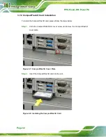
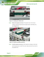
Figure 3-18: Installing the PCIe Riser Card
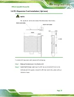
Step 3:
Remove the expansion slot cover
. The expansion slot on the I/O panel
interface is secured to the system with a single retention screw. Remove the
screw.
Figure 3-19: Expansion Slot Retention Screw
Step 4:
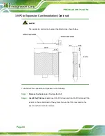
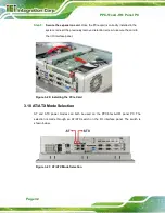
Insert the expansion card
. Align the PCIe expansion card edge connector with
the PCIe expansion slot on the PCIe riser card. Gently insert the PCIe card into
the PCIe expansion slot.
Summary of Contents for PPC-51 A-H61 Series
Page 11: ...PPC 51xxA H61 Panel PC Page xi Figure 6 2 Main Board Layout Diagram Solder Side 106 ...
Page 14: ...PPC 51xxA H61 Panel PC Page 1 1 Introduction Chapter 1 ...
Page 20: ...PPC 51xxA H61 Panel PC Page 7 Figure 1 5 PPC 5150A H61 PPC 5170A H61 Bottom View ...
Page 30: ...PPC 51xxA H61 Panel PC Page 17 2 Unpacking Chapter 2 ...
Page 35: ...PPC 51xxA H61 Panel PC Page 22 3 Installation Chapter 3 ...
Page 49: ...PPC 51xxA H61 Panel PC Page 36 Figure 3 14 Replacing the Optical Drive Bracket ...
Page 75: ...PPC 51xxA H61 Panel PC Page 62 Chapter 4 4 System Maintenance ...
Page 84: ...PPC 51xxA H61 Panel PC Page 71 5 BIOS Setup Chapter 5 ...
Page 117: ...PPC 51xxA H61 Panel PC Page 104 6 Interface Connectors Chapter 6 ...
Page 136: ...PPC 51xxA H61 Panel PC Page 123 Appendix A A Regulatory Compliance ...
Page 141: ...PPC 51xxA H61 Panel PC Page 128 B BIOS Configuration Options Appendix B ...
Page 144: ...PPC 51xxA H61 Panel PC Page 131 C Safety Precautions Appendix C ...
Page 149: ...PPC 51xxA H61 Panel PC Page 136 D Watchdog Timer Appendix D ...
Page 152: ...PPC 51xxA H61 Panel PC Page 139 E Hazardous Materials Disclosure Appendix E ...


