PPC-51xxA-H61 Panel PC
Page 48
Step 3:
Slide the PPC-51xxA-H61 through the hole until the metal frame is flush against
the panel.
Step 4:
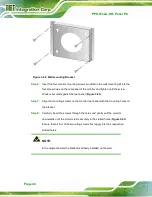
Insert the panel mounting clamps into the pre-formed holes along the edges of
the PPC-51xxA-H61, behind the aluminum frame (
6
Figure 3-28
). Refer to the
mounting kit packing list for the required number of mounting clamps.
Figure 3-28: Panel Mounting Clamp Positions
Step 5:
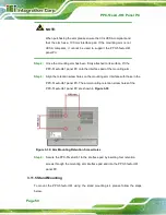
Tighten the screws that pass through the panel mounting clamps until the plastic
caps at the front of all the screws are firmly secured to the panel (
6
Figure 3-29
).
Summary of Contents for PPC-51 A-H61 Series
Page 11: ...PPC 51xxA H61 Panel PC Page xi Figure 6 2 Main Board Layout Diagram Solder Side 106 ...
Page 14: ...PPC 51xxA H61 Panel PC Page 1 1 Introduction Chapter 1 ...
Page 20: ...PPC 51xxA H61 Panel PC Page 7 Figure 1 5 PPC 5150A H61 PPC 5170A H61 Bottom View ...
Page 30: ...PPC 51xxA H61 Panel PC Page 17 2 Unpacking Chapter 2 ...
Page 35: ...PPC 51xxA H61 Panel PC Page 22 3 Installation Chapter 3 ...
Page 49: ...PPC 51xxA H61 Panel PC Page 36 Figure 3 14 Replacing the Optical Drive Bracket ...
Page 75: ...PPC 51xxA H61 Panel PC Page 62 Chapter 4 4 System Maintenance ...
Page 84: ...PPC 51xxA H61 Panel PC Page 71 5 BIOS Setup Chapter 5 ...
Page 117: ...PPC 51xxA H61 Panel PC Page 104 6 Interface Connectors Chapter 6 ...
Page 136: ...PPC 51xxA H61 Panel PC Page 123 Appendix A A Regulatory Compliance ...
Page 141: ...PPC 51xxA H61 Panel PC Page 128 B BIOS Configuration Options Appendix B ...
Page 144: ...PPC 51xxA H61 Panel PC Page 131 C Safety Precautions Appendix C ...
Page 149: ...PPC 51xxA H61 Panel PC Page 136 D Watchdog Timer Appendix D ...
Page 152: ...PPC 51xxA H61 Panel PC Page 139 E Hazardous Materials Disclosure Appendix E ...

