PPC-5150GS Flat Panel PC
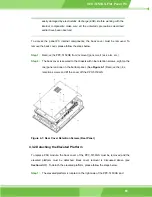
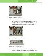
Figure 4-8: PSU Motherboard Connector
Step 5:
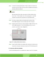
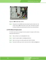
The PSU module is secured to the PPC-5150GS flat panel PC with four
retention screws, two connect to the metal sheet at the back of the 15”TFT LCD
screen (
Figure 4-9
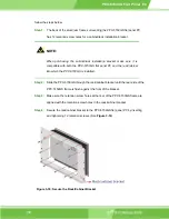
) and the other two are inserted through the bottom panel and
into the PSU module (
Figure 4-10
). Remove these four retention screws.
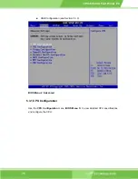
Figure 4-9: PSU Internal Retention Screws
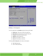
Figure 4-10: PSU External Retention Screws
Step 6:
Remove the PSU module from the PPC-5150GS flat panel PC. The PSU
module cables are connected together with ties. This is to help save space in the
69
Summary of Contents for PPC-5150GS
Page 1: ...PPC 5150GS Flat Panel PC 1 PPC 5150 Flat Panel PC ...
Page 17: ...PPC 5150GS Flat Panel PC Chapter 1 1 Introduction 17 ...
Page 29: ...PPC 5150GS Flat Panel PC 29 Figure 1 8 Dimensions units in mm ...
Page 30: ...PPC 5150GS Flat Panel PC THIS PAGE IS INTENTIONALLY LEFT BLANK IEI Technology Corp 30 ...
Page 31: ...PPC 5150GS Flat Panel PC 2 POS 8520 Motherboard Chapter 2 31 ...
Page 38: ...PPC 5150GS Flat Panel PC THIS PAGE IS INTENTIONALLY LEFT BLANK IEI Technology Corp 38 ...
Page 39: ...PPC 5150GS Flat Panel PC 3 Installation and Configuration Chapter 3 39 ...
Page 63: ...PPC 5150GS Flat Panel PC Chapter 4 4 System Maintenance 63 ...
Page 71: ...PPC 5150GS Flat Panel PC 5 AMI BIOS Chapter 5 71 ...
Page 125: ...PPC 5150GS Flat Panel PC Appendix A A Interface Connectors 125 ...
Page 142: ...PPC 5150GS Flat Panel PC THIS PAGE IS INTENTIONALLY LEFT BLANK IEI Technology Corp 142 ...
Page 143: ...PPC 5150GS Flat Panel PC Appendix B B BIOS Configuration Options 143 ...
Page 148: ...PPC 5150GS Flat Panel PC THIS PAGE IS INTENTIONALLY LEFT BLANK IEI Technology Corp 148 ...
Page 149: ...PPC 5150GS Flat Panel PC Appendix C C Software Drivers 149 ...
Page 158: ...PPC 5150GS Flat Panel PC THIS PAGE IS INTENTIONALLY LEFT BLANK IEI Technology Corp 158 ...
Page 159: ...PPC 5150GS Flat Panel PC Appendix D D IEI Panel PC Product Line 159 ...

