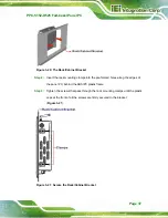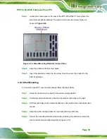
PPC-5152-D525 Falt-bezel Panel PC
Page 26
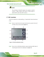
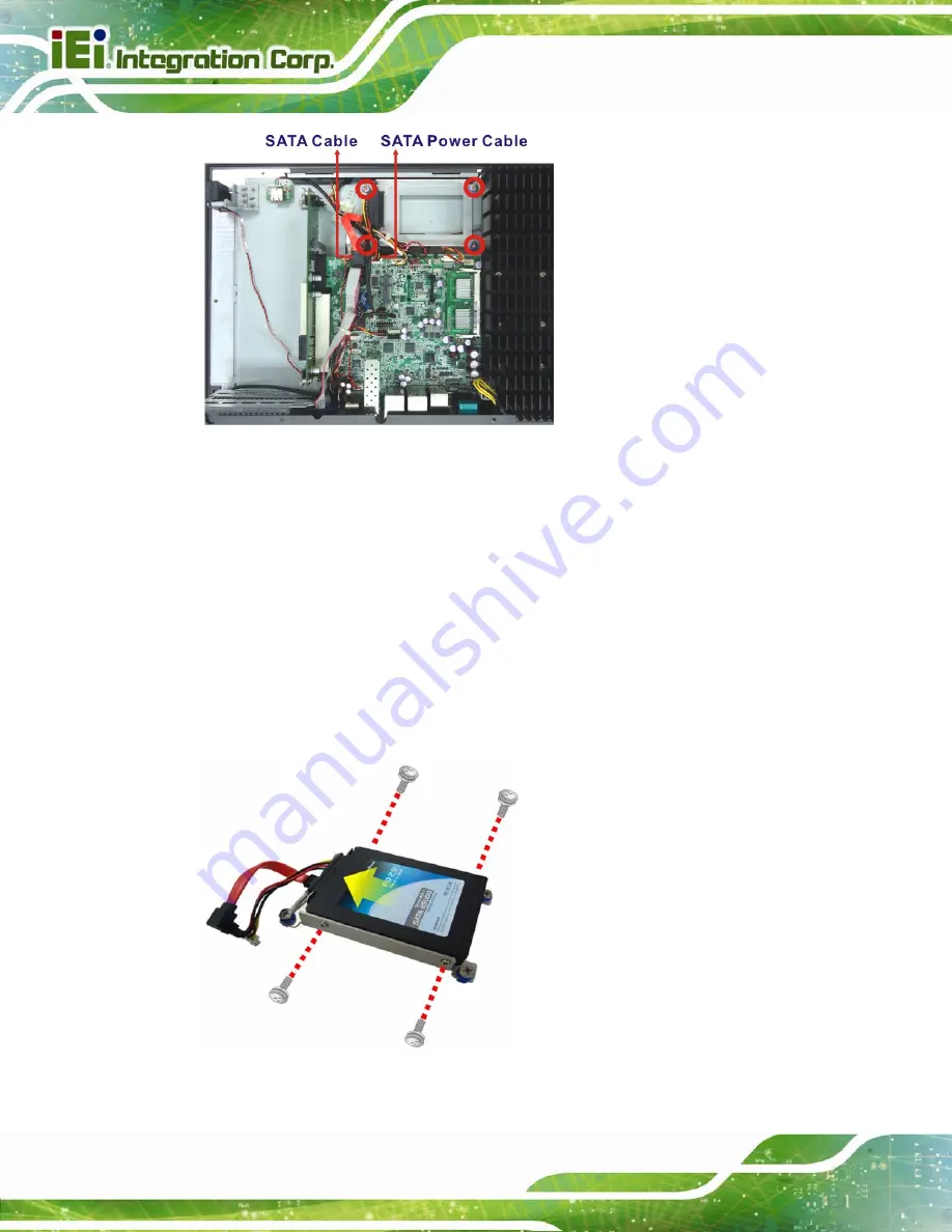
Figure 3-8: HDD Bracket Retention Screws
Step 3:
Lift the HDD bracket out of the PPC-5152-D525.
Step 4:
Remove the SATA connector from the bracket by removing the two retention
screws on the bottom of the bracket.
Step 5:
Connect the HDD to the SATA connector first, then place the HDD onto the
bracket. Secure the SATA connector with the HDD bracket by two previously
removed screws.
Step 6:
Secure the HDD with the HDD bracket by four retention screws (
6
Figure 3-9
).
Figure 3-9: HDD Installation
Summary of Contents for PPC-5152-D525
Page 15: ...PPC 5152 D525 Falt bezel Panel PC Page 1 1 Introduction Chapter 1 ...
Page 29: ...PPC 5152 D525 Falt bezel Panel PC Page 15 2 Unpacking Chapter 2 ...
Page 33: ...PPC 5152 D525 Falt bezel Panel PC Page 19 3 Installation Chapter 3 ...
Page 71: ...PPC 5152 D525 Falt bezel Panel PC Page 57 Chapter 4 4 System Maintenance ...
Page 79: ...PPC 5152 D525 Falt bezel Panel PC Page 65 5 AMI BIOS Setup Chapter 5 ...
Page 108: ...PPC 5152 D525 Falt bezel Panel PC Page 94 6 Software Drivers Chapter 6 ...
Page 130: ...PPC 5152 D525 Falt bezel Panel PC Page 116 A BIOS Configuration Options Appendix A ...
Page 133: ...PPC 5152 D525 Falt bezel Panel PC Page 119 Appendix B B One Key Recovery ...
Page 141: ...PPC 5152 D525 Falt bezel Panel PC Page 127 Figure B 5 Partition Creation Commands ...
Page 174: ...PPC 5152 D525 Falt bezel Panel PC Page 160 C Safety Precautions Appendix C ...
Page 179: ...PPC 5152 D525 Falt bezel Panel PC Page 165 D Watchdog Timer Appendix D ...
Page 182: ...PPC 5152 D525 Falt bezel Panel PC Page 168 E Hazardous Materials Disclosure Appendix E ...


