PPC-51xxA-H61 Panel PC
Page 108
Connector
Type
Label
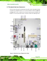
SPI Flash connector
8-pin header
JSPI1
Touch panel connector
9-pin wafer
TOUCH1
USB 2.0 connectors
8-pin header
USB1, USB2,
USB3, USB4
Table 6-1: Peripheral Interface Connectors
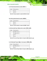
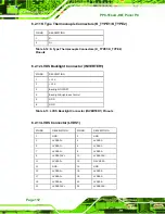
6.2.1 +12V Power Source Connector (CPU12V1)
6.2.2 ATX Power Connector (ATX1)
PIN NO.
DESCRIPTION
PIN NO.
DESCRIPTION
1 +3.3V 13
+3.3V
2 +3.3V 14
-12V
3 GND
15
GND
4 +5V
16
PS_ON-
5 GND
17
GND
6 +5V
18
GND
7 GND
19
GND
8 NC
20
NC
9 +5V
21
+5V
10 +12V
22 +5V
11 +12V
23 +5V
12 +3.3V
24 GND
PIN NO.
DESCRIPTION
1 GND
2 GND
3 +12V
4 +12V
Table 6-2: +12V Power Source Connector ( CPU12V1) Pinouts
Table 6-3: ATX Power Connector (ATX1) Pinouts
Summary of Contents for PPC-51xxA-H61
Page 16: ...PPC 51xxA H61 Panel PC Page 1 1 Introduction Chapter 1 ...
Page 22: ...PPC 51xxA H61 Panel PC Page 7 Figure 1 5 PPC 5150A H61 PPC 5170A H61 Bottom View ...
Page 32: ...PPC 51xxA H61 Panel PC Page 17 2 Unpacking Chapter 2 ...
Page 37: ...PPC 51xxA H61 Panel PC Page 22 3 Installation Chapter 3 ...
Page 51: ...PPC 51xxA H61 Panel PC Page 36 Figure 3 14 Replacing the Optical Drive Bracket ...
Page 77: ...PPC 51xxA H61 Panel PC Page 62 Chapter 4 4 System Maintenance ...
Page 86: ...PPC 51xxA H61 Panel PC Page 71 5 BIOS Setup Chapter 5 ...
Page 119: ...PPC 51xxA H61 Panel PC Page 104 6 Interface Connectors Chapter 6 ...
Page 138: ...PPC 51xxA H61 Panel PC Page 123 A BIOS Configuration Options Appendix A ...
Page 141: ...PPC 51xxA H61 Panel PC Page 126 Appendix B B One Key Recovery ...
Page 149: ...PPC 51xxA H61 Panel PC Page 134 Figure B 5 Partition Creation Commands ...
Page 182: ...PPC 51xxA H61 Panel PC Page 167 C Safety Precautions Appendix C ...
Page 187: ...PPC 51xxA H61 Panel PC Page 172 D Watchdog Timer Appendix D ...
Page 190: ...PPC 51xxA H61 Panel PC Page 175 E Hazardous Materials Disclosure Appendix E ...


