PPC-5xxx-9455 Panel PC
Page 148
Step 5:
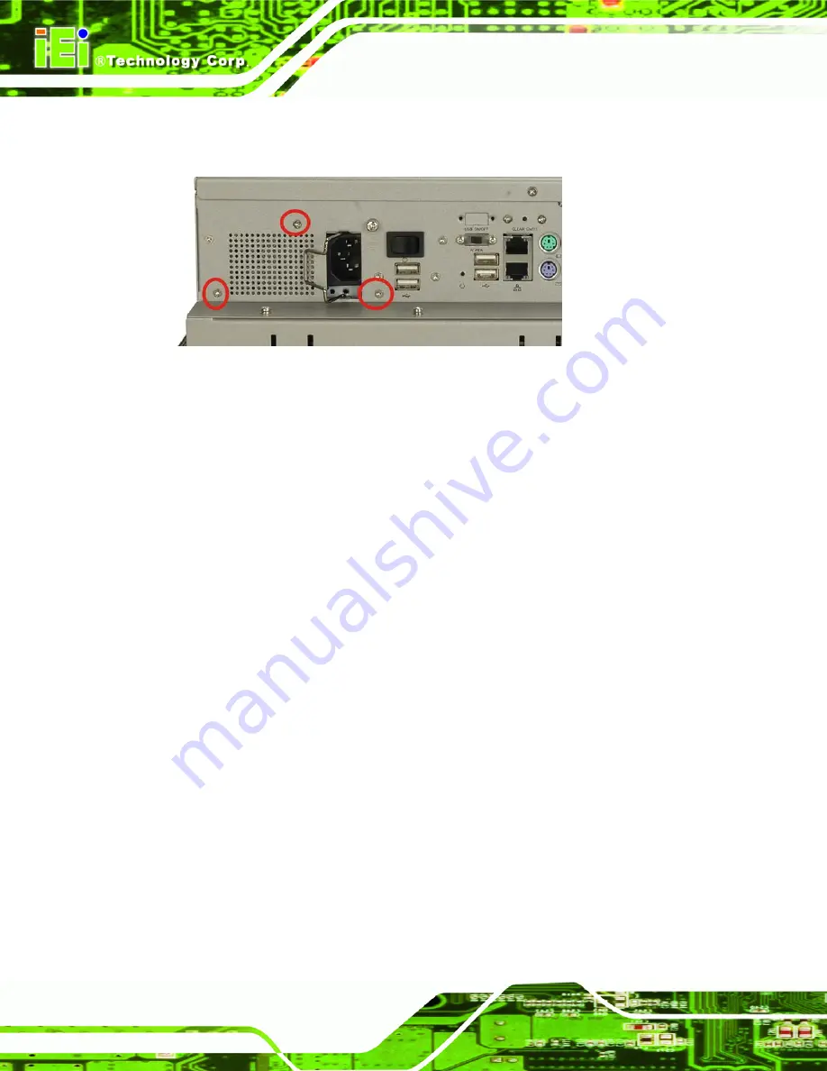
Remove the retention screws that connect the PSU bracket to the chassis
(
).
Figure 7-8: PSU Rear Panel Screws
Step 6:
Remove the retention screws that connect the PSU to the PSU bracket.
Step 0:
7.6.2 Install the New PSU
Installation is done in the reverse order to removal. To install a new PSU module, please
follow the steps below.
Step 1:
Attach the PSU bracket to the PSU module with the previously removed
retention screws.
Step 2:
Insert the PSU module and bracket assembly into the chassis and attach the
PSU bracket to the chassis with the previously removed retention screws.
Step 3:
Secure the PSU module to the chassis by reinserting the previously removed
retention screws through the bottom panel.
Step 4:
Bundle the cables of the new PSU module and secure them with a plastic tie
similar to the old PSU module.
Step 5:
Reconnect all previously disconnected power connectors to the motherboard
and disk drives.
Step 6:
Reattach the elevated platform.
Step 7:
Replace the back cover.
Step 0:
Summary of Contents for PPC-5xxx-9455
Page 1: ...PPC 5xxx 9455 Panel PC Page i ...
Page 2: ...PPC 5xxx 9455 Panel PC Page ii Revision Date Version Changes August 2008 1 00 Initial release ...
Page 12: ...PPC 5xxx 9455 Panel PC Page xii ROHS COMPLIANT UNDER 2002 95 EC WITHOUT MERCURY 175 ...
Page 18: ......
Page 19: ...PPC 5xxx 9455 Panel PC Page 1 Chapter 1 1 Introduction ...
Page 27: ...PPC 5xxx 9455 Panel PC Page 9 Chapter 2 2 Specifications ...
Page 51: ...PPC 5xxx 9455 Panel PC Page 33 Chapter 3 3 Unpacking ...
Page 55: ...PPC 5xxx 9455 Panel PC Page 37 Chapter 4 4 Installation and Configuration ...
Page 83: ...PPC 5xxx 9455 Panel PC Page 65 Chapter 5 5 BIOS Setup ...
Page 88: ...PPC 5xxx 9455 Panel PC Page 70 BIOS Menu 2 Advanced ...
Page 129: ...PPC 5xxx 9455 Panel PC Page 111 BIOS Menu 20 CD DVD Drives ...
Page 137: ...PPC 5xxx 9455 Panel PC Page 119 Chapter 6 6 Software Installation ...
Page 159: ...PPC 5xxx 9455 Panel PC Page 141 Chapter 7 7 System Maintenance ...
Page 169: ...PPC 5xxx 9455 Panel PC Page 151 Appendix A A BIOS Options ...
Page 173: ...PPC 5xxx 9455 Panel PC Page 155 Appendix B B Terminology ...
Page 177: ...PPC 5xxx 9455 Panel PC Page 159 Appendix C C Digital I O Interface ...
Page 180: ...PPC 5xxx 9455 Panel PC Page 162 Appendix D D Watchdog Timer ...
Page 183: ...PPC 5xxx 9455 Panel PC Page 165 Appendix E E Address Mapping ...
Page 185: ...PPC 5xxx 9455 Panel PC Page 167 E 2 Input Output IO Figure E 2 Input Output IO 1 of 2 ...
Page 186: ...PPC 5xxx 9455 Panel PC Page 168 Figure E 3 Input Output IO 2 of 2 ...
Page 187: ...PPC 5xxx 9455 Panel PC Page 169 E 3 Interrupt Request IRQ Figure E 4 Interrupt Request IRQ ...
Page 188: ...PPC 5xxx 9455 Panel PC Page 170 E 4 Memory Figure E 5 Memory ...
Page 189: ...PPC 5xxx 9455 Panel PC Page 171 Appendix F F Compatibility ...
Page 192: ...PPC 5xxx 9455 Panel PC Page 174 Appendix G G Hazardous Materials Disclosure ...


