background image


PPC-FxxC-Q370 


Page 95 

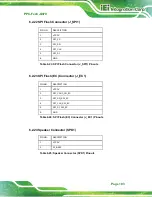
Connector 

Type 

Label 

SATA 6Gb/s connectors 

SATA connector 

S_ATA5, S_ATA6 

SMBus connector 

4-pin wafer 

SMB1 

SPI flash connector 

6-pin wafer 

J_SPI1 

SPI flash (EC) connector   

6-pin wafer 

J_EC1 

Speaker connector 

2-pin wafer 

SPK1 

TPM connector 

20-pin header 

TPM1 

USB 2.0 connectors (single) 

4-pin wafer 

JUSB1, JUSB2 

USB 2.0 connector (dual) 

8-pin header 

JUSB3 

USB DOM connector 

8-pin header 

USB_DOM1 

Table 6-1: Peripheral Interface Connectors 


6.2.1 ATX Power Input Connector (ATX1) 

PIN NO. 

DESCRIPTION 

PIN NO. 

DESCRIPTION 

VCC3V 

13 

VCC3V 

VCC3V 

14 

-VCC12V 

GND 

15 

GND 

VCC5V 

16 

PS_ON 

GND 

17 

GND 

VCC5V 

18 

GND 

GND 

19 

GND 

PWR_OK 

20 

NC 

SB5V 

21 

VCC5V 

10 

VCC12V 

22 

VCC5V 

11 

VCC12V 

23 

VCC5V 

12 

VCC3V 

24 

GND 

Table 6-2: ATX Power Input Connector (ATX1) Pinouts 


Summary of Contents for PPC-F C-Q370 Series

Page 1: ...l ePPC FxxC Q370 Panel PC MODEL MODEL PPC FxxC Q370 Modular Panel PC with 8th Gen LGA1151 Intel Core i7 i5 i3 and Pentium Processor DDR4 HDMI USB 3 2 Dual GbE RS 232 M 2 Four SSD Bays PCIe 3 0 RoHS Compliant Rev 1 02 January 31 2020 ...

Page 2: ...70 Page ii Revision Date Version Changes January 31 2020 1 02 Added a note in Section 1 5 regarding to the USB power consumption March 18 2019 1 01 Updated bottom panel photos November 2 2018 1 00 Initial release ...

Page 3: ...rate it in an area that exceeds the maximum operating temperature described in the user manual Vorsicht Um eine Überhitzung des Systems zu vermeiden betreiben Sie es ausschließlich im zulässigen Betriebstemperaturbereich Dieser ist in der Bedienungsanleitung vermerkt Attention Pour éviter la surchauffe du système ne l utilisez pas dans une zone dont la température dépasse les limites décrits dans ...

Page 4: ... La mise au rebut ou le recyclage de ce produit sont généralement soumis aux lois et ou directives de respect de l environnement Renseignez vous auprès de l organisme compétent Avvertenza Lo smaltimento di questo prodotto deve essere eseguito secondo le leggi e i regolamenti locali Atención La disposición final de residuos de este producto se debe cumplir con las normativas y leyes del país 警告 本產品...

Page 5: ...sing out of the use or inability to use the product or documentation even if advised of the possibility of such damages This document contains proprietary information protected by copyright All rights are reserved No part of this manual may be reproduced by any mechanical electronic or other means in any form without prior written permission of the manufacturer TRADEMARKS All registered trademarks...

Page 6: ...ury Warnings should be taken seriously CAUTION Cautionary messages should be heeded to help reduce the chance of losing data or damaging the product NOTE These messages inform the reader of essential but non critical information These messages should be read carefully as any directions or instructions contained therein can help avoid making mistakes ...

Page 7: ...ensions 11 1 8 2 PPC FW15C Q370 Dimensions 12 1 8 3 PPC F17C Q370 Dimensions 13 1 8 4 PPC FW19C Q370 Dimensions 14 1 8 5 PPC FW22C Q370 Dimensions 15 1 8 6 PPC FW24C Q370 Dimensions 16 2 UNPACKING 17 2 1 UNPACKING 18 2 2 PACKING LIST 18 2 3 OPTIONAL ITEMS 19 3 INSTALLATION 20 3 1 ANTI STATIC PRECAUTIONS 21 3 2 INSTALLATION PRECAUTIONS 21 3 3 INSTALLATION PROCEDURE 22 3 4 SOLID STATE DRIVE INSTALLA...

Page 8: ...46 4 1 1 Starting Setup 46 4 1 2 Using Setup 46 4 1 3 Getting Help 47 4 1 4 BIOS Menu Bar 47 4 2 MAIN 48 4 3 ADVANCED 49 4 3 1 CPU Configuration 51 4 3 2 Thunderbolt Configuration 53 4 3 3 Trusted Computing 54 4 3 4 ACPI Settings 55 4 3 5 iWDD H W Monitor 56 4 3 5 1 Smart Fan Mode Configuration 57 4 3 6 F81866 Super IO Configuration 59 4 3 6 1 Serial Port n Configuration 60 4 3 7 RTC Wake Settings...

Page 9: ... 89 5 2 1 The System Doesn t Turn On 89 5 2 2 The System Doesn t Boot Up 90 5 2 3 More Troubleshooting 90 5 3 COMPONENT REPLACEMENT 91 6 INTERFACE CONNECTORS 92 6 1 PERIPHERAL INTERFACE CONNECTORS 93 6 2 INTERNAL PERIPHERAL CONNECTORS 94 6 2 1 ATX Power Input Connector ATX1 95 6 2 2 Additional Power Connector ATXPWR1 96 6 2 3 Battery Connector BAT1 96 6 2 4 Chassis Intrusion Connector CHASSIS1 96 ...

Page 10: ... 103 6 2 24 Speaker Connector SPK1 103 6 2 25 TPM Connector TPM1 104 6 2 26 USB 2 0 Connectors Single JUSB1 JUSB2 104 6 2 27 USB 2 0 Connectors Dual JUSB3 105 6 2 28 USB DOM Connector USB_DOM1 105 6 3 JUMPERS 105 6 3 1 Clear CMOS Jumper J_CMOS1 106 6 3 2 ME RTC Register Setting Jumper ME_RTC1 106 A REGULATORY COMPLIANCE 107 B SAFETY PRECAUTIONS 112 B 1 SAFETY PRECAUTIONS 113 B 1 1 General Safety P...

Page 11: ...PPC FxxC Q370 Page xi E ERROR BEEP CODE 124 E 1 PEI BEEP CODES 125 E 2 DXE BEEP CODES 125 F HAZARDOUS MATERIALS DISCLOSURE 126 F 1 ROHS II DIRECTIVE 2015 863 EU 127 F 2 CHINA ROHS 128 ...

Page 12: ...5 Rear Cover Retention Screw Removal 26 Figure 3 6 Remove the Rear Cover 26 Figure 3 7 DIMM Installation 27 Figure 3 8 DIMM Slot Locations 27 Figure 3 9 M 2 Slot Locations 28 Figure 3 10 Removing the M 2 Module Retention Screw 29 Figure 3 11 Inserting the M 2 Module into the Slot at an Angle 29 Figure 3 12 Securing the M 2 Module 30 Figure 3 13 PCIe Slot Locations 31 Figure 3 14 Blank Bracket Scre...

Page 13: ...ket 36 Figure 3 24 Secure the Rack Cabinet Bracket 36 Figure 3 25 Install into a Rack Cabinet 37 Figure 3 26 RS 232 Connector COM1 COM2 38 Figure 3 27 Power Button 39 Figure 3 28 IEI Resource Download Center 40 Figure 3 29 RAID Configuration BIOS Setting 43 Figure 6 1 Main Board Layout Diagram Front Side 93 ...

Page 14: ...Debug Port EC_DBG1 Pinouts 97 Table 6 9 CPU Fan Connector CPU_FAN1 Pinouts 97 Table 6 10 System Fan Connectors SYS_FAN1 SYS_FAN2 SYS_FAN3 Pinouts 98 Table 6 11 I2 C Connector I2C1 Pinouts 98 Table 6 12 Internal DisplayPort Connector IDP1 Pinouts 98 Table 6 13 HDD LED Connector H_LED1 Pinouts 99 Table 6 14 Power LED Connector P_LED1 Pinouts 99 Table 6 15 LVDS Connector LVDS1 Pinouts 100 Table 6 16 ...

Page 15: ...inouts 104 Table 6 27 Single USB 2 0 Connectors JUSB1 JUSB2 Pinouts 104 Table 6 28 Dual USB 2 0 Connector JUSB3 Pinouts 105 Table 6 29 USB DOM Connector USB_DOM1 Pinouts 105 Table 6 30 Jumpers 105 Table 6 31 Clear CMOS Jumper J_CMOS1 Settings 106 Table 6 32 ME RTC Register Jumper ME_RTC1 Settings 106 ...

Page 16: ...Redirection 62 BIOS Menu 13 Legacy Console Redirection Settings 65 BIOS Menu 14 USB Configuration 66 BIOS Menu 15 NVMe Configuration 67 BIOS Menu 16 IEI QTS 67 BIOS Menu 17 IEI Feature 68 BIOS Menu 18 Chipset 69 BIOS Menu 19 System Agent SA Configuration 70 BIOS Menu 20 Memory Configuration 71 BIOS Menu 21 Graphics Configuration 72 BIOS Menu 22 PEG Port Configuration 74 BIOS Menu 23 PEG Port Featu...

Page 17: ...PPC FxxC Q370 Page xvii BIOS Menu 31 Save Exit 87 ...

Page 18: ......

Page 19: ...PPC FxxC Q370 Page 1 Chapter 1 1 Introduction ...

Page 20: ... The excellent active cooling method is utilized to effectively transfer heat from the chassis and maintain system performance The PPC FxxC Q370 includes four low profile PCIe slots for various expansions two of them are PCIe 3 0 x8 slots for adding GPU cards or image processing cards for high performance Artificial Intelligence computing Four 2 5 SATA SSD bays with RAID function are protected in ...

Page 21: ... 17 1280x1024 Intel Core i3 8100T PPC F17C Q370 i5 PC 25 17 1280x1024 Intel Core i5 8500T PPC F17C Q370 i7 PC 25 17 1280x1024 Intel Core i7 8700T PPC FW19C Q370 P PC 25 18 5 1366x768 Intel Pentium Gold G5400T PPC FW19C Q370 i3 PC 25 18 5 1366x768 Intel Core i3 8100T PPC FW19C Q370 i5 PC 25 18 5 1366x768 Intel Core i5 8500T PPC FW19C Q370 i7 PC 25 18 5 1366x768 Intel Core i7 8700T PPC FW22C Q370 P ...

Page 22: ...4 memory Four PCIe 3 0 slots for expansion Four hot swappable 2 5 SATA HDD SSD bays Two M 2 M key 2280 slots support NVMe SSD Two GbE LAN Various I O interfaces including six USB 3 2 Gen 1 ports one RS 232 port HDMI output audio line out and mic in RoHS compliant design 1 4 Front Panel The front side of the PPC FxxC Q370 is a flat panel LCD with P CAP touchscreen surrounded by a metal frame Figure...

Page 23: ...Gen 1 port on the PPC FxxC Q370 s bottom panel can supply 900mA power However if these six USB ports are all connected to devices when booting up the system could fail to startup due to the sudden load increase To solve this problem it is recommended to set USB Power SW1 to 5V in BIOS Chipset PCH IO Configuration Refer to Section 4 4 2 ...

Page 24: ...6 1 6 Top Panel The top panel of the PPC FxxC Q370 has the following button and indicator 1 x Power button with power LED indicator power on solid blue 1 x HDD LED indicator HDD activity blinking red Figure 1 4 Top Panel ...

Page 25: ...EXC3000 Anti glare Coating Yes No CPU 8th Generation LGA1151 Intel Core i7 i5 i3 and Pentium CPU Chipset Intel Q370 BIOS AMI UEFI BIOS Memory Two 288 pin 2666 2400 MHz dual channel unbuffered DDR4 SDRAM DIMM slots system max 64 GB Graphics Engine Intel HD Graphics Gen 9 Engines with low power 16 execution units supports DX2015 OpenGL 5 X and OpenCL2 x ES 2 0 Ethernet Two Intel I211AT Ethernet cont...

Page 26: ...ad 50 90 Light load 20 87 Dimensions WxHxD 378 5 x 303 x 118 mm 400 x 253 x 121 mm 409 x 342 x 119 mm Cutout Dimensions 361 1 x 285 6 mm 379 1 x 232 3 mm 391 x 324 mm Chassis Construction Metal housing Color Front frame Cyan blue PSM 296C Others Black C Mounting Panel Rack mount Watchdog Timer Software programmable support 1 255 sec system reset Vibration 5 17Hz 0 1 double amplitude displacement 1...

Page 27: ...ng No Yes CPU 8th Generation LGA1151 Intel Core i7 i5 i3 and Pentium CPU Chipset Intel Q370 BIOS AMI UEFI BIOS Memory Two 288 pin 2666 2400 MHz dual channel unbuffered DDR4 SDRAM DIMM slots system max 64 GB Graphics Engine Intel HD Graphics Gen 9 Engines with low power 16 execution units supports DX2015 OpenGL 5 X and OpenCL2 x ES 2 0 Ethernet Two Intel I211AT Ethernet controllers LAN1 LAN2 Super ...

Page 28: ...oad 20 87 Dimensions WxHxD 470 x 290 x 121 mm 551 x 359 x 118 mm 600 x 382 x 119 mm Cutout Dimensions 447 8 x 267 2 mm 533 x 341 mm 577 6 x 359 6 mm Chassis Construction Metal housing Color Front frame Cyan blue PSM 296C Others Black C Mounting Panel Rack mount Watchdog Timer Software programmable support 1 255 sec system reset Vibration 5 17Hz 0 1 double amplitude displacement 17 640Hz 1 5G accel...

Page 29: ...PPC FxxC Q370 Page 11 1 8 Dimensions 1 8 1 PPC F15C Q370 Dimensions Figure 1 5 PPC F15C Q370 Dimensions Unit mm ...

Page 30: ...PPC FxxC Q370 Page 12 1 8 2 PPC FW15C Q370 Dimensions Figure 1 6 PPC FW15C Q370 Dimensions Unit mm ...

Page 31: ...PPC FxxC Q370 Page 13 1 8 3 PPC F17C Q370 Dimensions Figure 1 7 PPC F17C Q370 Dimensions Unit mm ...

Page 32: ...PPC FxxC Q370 Page 14 1 8 4 PPC FW19C Q370 Dimensions Figure 1 8 PPC FW19C Q370 Dimensions Unit mm ...

Page 33: ...PPC FxxC Q370 Page 15 1 8 5 PPC FW22C Q370 Dimensions Figure 1 9 PPC FW22C Q370 Dimensions Unit mm ...

Page 34: ...PPC FxxC Q370 Page 16 1 8 6 PPC FW24C Q370 Dimensions Figure 1 10 PPC FW24C Q370 Dimensions Unit mm ...

Page 35: ...PPC FxxC Q370 Page 17 Chapter 2 2 Unpacking ...

Page 36: ...system out of the boxes Step 5 Remove both polystyrene ends one from each side Step 6 Make sure all the components listed in the packing list are present 2 2 Packing List NOTE If any of the components listed in the checklist below are missing do not proceed with the installation Contact the IEI reseller or vendor the PPC FxxC Q370 was purchased from or contact an IEI sales representative directly ...

Page 37: ...lowing items are optional accessories for the PPC FxxC Q370 Panel mount kit PPC F15C PPC FW15C PPC F17C FPK 12 R10 FPK 14 R10 FPK 13 R10 PPC FW19C PPC FW22C PPC FW24C FPK 13 R10 FPK 13 R10 FPK 14 R10 Rack mount kit PPC F15C PPC FW15C PPC F17C FRK15C R10 FRKW15C R10 FRK17C R10 PPC FW19C PPC FW22C PPC FW24C FRKW19C R10 N A N A Table 2 2 Optional Items ...

Page 38: ...PPC FxxC Q370 Page 20 Chapter 3 3 Installation ...

Page 39: ...ng Before handling the board touch any grounded conducting material During the time the board is handled frequently touch any conducting materials that are connected to the ground Use an anti static pad When configuring the PPC FxxC Q370 place it on an anti static pad This reduces the possibility of ESD damaging the PPC FxxC Q370 3 2 Installation Precautions During installation be aware of the pre...

Page 40: ...erly grounded The voltage feeds must not be overloaded Adjust the cabling and provide external overcharge protection per the electrical values indicated on the label attached to the back of the PPC FxxC Q370 3 3 Installation Procedure To properly install the PPC FxxC Q370 the following steps must be followed Detailed descriptions of these instructions are listed in the sections that follow Step 1 ...

Page 41: ... drive trays protected by a lockable cover on the bottom panel To install the SSD into the system please follow the steps below Step 1 Unlock the HDD cover on the bottom panel with the key came with the system Figure 3 1 Unlock HDD Cover Step 2 Open the HDD cover and you will see four drive trays Figure 3 2 Pull out one of the drive trays Figure 3 2 Drive Tray Removal ...

Page 42: ...of the SSD Figure 3 3 Figure 3 3 SSD Retention Screws Step 4 Carefully insert the SSD into the slot Make sure the SATA connector on the SSD is securely connected to the SATA connector inside the chassis Figure 3 4 SSD Installation Step 5 Repeat Step 2 Step 4 described above to install another SSD Step 6 Close the HDD cover and lock it with the key Step 0 ...

Page 43: ...ied out on the system make sure the system is turned off and cooled down for 5 minutes Failing to turn off the system before opening it can cause permanent damage to the system and serious or fatal injury to the user To access the PPC FxxC Q370 internally the rear cover must be removed To remove the rear cover please follow the steps below Step 1 Remove the six retention screws two on the bottom a...

Page 44: ...e 3 5 Rear Cover Retention Screw Removal Step 2 Slide the rear cover towards the I O panel until it is disengaged from the locking mechanism Then lift the rear cover off the chassis See Figure 3 6 Figure 3 6 Remove the Rear Cover ...

Page 45: ...IMM Installation Step 1 Remove the rear cover See Section 3 5 above Step 2 Locate the DIMM slots as shown in Figure 3 8 Figure 3 8 DIMM Slot Locations Step 3 Open the two handles outwards as far as they can See Figure 3 7 Step 4 Align the DIMM so the notch on the memory lines up with the notch on the memory socket See Figure 3 7 ...

Page 46: ...onfiguration install two identical memory modules that feature the same capacity timings voltage number of ranks and the same brand 3 7 M 2 SSD Installation Optional The two M 2 M key slots allow installation of M 2 2280 cards To install an M 2 card please follow the steps below Step 1 Remove the rear cover See Section 3 5 above Step 2 Locate the M 2 slot as shown in Figure 3 9 Figure 3 9 M 2 Slot...

Page 47: ... the notch on the module with the notch on the slot Slide the M 2 module into the socket at an angle of about 20º Figure 3 11 Figure 3 11 Inserting the M 2 Module into the Slot at an Angle Step 5 Push the M 2 module down and secure it with the previously removed retention screw Figure 3 12 ...

Page 48: ...moved 3 8 Expansion Card Installation Optional The PPC FxxC Q370 supports multiple PCIe slots which are compatible with standard low profile add on cards including two PCIe 3 0 x16 x8 mode and two PCIe 3 0 x4 slots To install an expansion card follow the steps below Step 1 Remove the rear cover See Section 3 5 above Step 2 Locate an empty PCIe slot ...

Page 49: ... Page 31 Figure 3 13 PCIe Slot Locations Step 3 Remove the blank bracket panel on the bottom of the PPC FxxC Q370 that aligns with the empty PCIe slot Save this bracket screw Figure 3 14 Blank Bracket Screw Removal ...

Page 50: ... rear cover and secure it with the six retention screws previously removed 3 9 Mounting the System The following sections describe the mounting methods supported by the PPC FxxC Q370 3 9 1 Panel Mounting To mount the PPC FxxC Q370 panel PC into a panel please follow the steps below Step 1 Select the position on the panel to mount the PPC FxxC Q370 Step 2 Cut out a section of the panel that corresp...

Page 51: ...PPC FxxC Q370 Page 33 Figure 3 16 PPC F15C Q370 Panel Cutout Dimensions Figure 3 17 PPC FW15C Q370 Panel Cutout Dimensions Figure 3 18 PPC F17C Q370 Panel Cutout Dimensions ...

Page 52: ...C FW19C Q370 Panel Cutout Dimensions Figure 3 20 PPC FW22C Q370 Panel Cutout Dimensions Figure 3 21 PPC FW24C Q370 Panel Cutout Dimensions Step 3 Slide the PPC FxxC Q370 through the hole until the aluminum frame is flush against the panel ...

Page 53: ...screws are firmly secured to the panel Figure 3 22 Step 0 Figure 3 22 Tighten the Mounting Clamp Screws 3 9 2 Rack and Cabinet Installation The PPC FxxC Q370 panel PC can be installed into a cabinet or rack The installation procedures are similar to the panel mounting installation To do this please follow the steps described in the following sections NOTE When purchasing the cabinet rack installat...

Page 54: ...racket Step 2 Insert the mounting clamps into the mounting brackets and pre formed holes along the edges of the front panel behind the frame Figure 3 24 The required number of mounting clamps may vary by models Step 3 Tighten the screws that pass through the mounting clamps until the plastic caps at the front of all the screws are firmly secured to the bracket Figure 3 24 Figure 3 24 Secure the Ra...

Page 55: ...t into a rack or cabinet Figure 3 25 Figure 3 25 Install into a Rack Cabinet Step 5 Once the panel PC with the attached rack cabinet bracket has been properly inserted into the rack or cabinet secure the front of the rack cabinet bracket to the front of the rack or cabinet Figure 3 25 Step 0 ...

Page 56: ...connectors for RS 232 serial port connection The pinouts for the RS 232 connectors COM1and COM2 are listed in the figure and table below Figure 3 26 RS 232 Connector COM1 COM2 PIN NO DESCRIPTION 1 DCD 2 RX 3 TX 4 DTR 5 GND 6 DSR 7 RTS 8 CTS 9 RI Table 3 1 RS 232 Connector Pinouts ...

Page 57: ... user To power on the panel PC please make sure of the following Memory modules are installed The rear cover is installed All peripheral devices are connected The system is securely mounted 3 11 2 Power on Procedure To power on the PPC FxxC Q370 please follow the steps below Step 1 Connect the power source to the power inlet on the bottom panel Step 2 Short press the power button on the top panel ...

Page 58: ...o find all the relevant software utilities and documentation Figure 3 28 IEI Resource Download Center 3 12 1 Driver Download To download drivers from IEI Resource Download Center follow the steps below Step 1 Go to https download ieiworld com Type PPC FxxC Q370 and press Enter Step 2 All product related software utilities and documentation will be listed You can choose Driver to filter the result ...

Page 59: ...ick the small arrow to find an individual driver and click the file name to download NOTE To install software from the downloaded ISO image file in Windows 8 8 1 or 10 double click the ISO file to mount it as a virtual drive to view its content On Windows 7 system an additional tool such as Virtual CD ROM Control Panel from Microsoft is needed to mount the file ...

Page 60: ...iled drive can then be correctly identified CAUTION Do not accidentally disconnect the SATA drive cables Carefully route the cables within the chassis to avoid system down time Step 1 Connect SATA drives to the system Connect two or more SATA drives to the system Make sure the drives have the same capacity are the same type and have the same speed NOTE Make sure the SATA drives are EXACTLY the sam...

Page 61: ... during the system boot process press Ctrl I when prompted to enter the RAID configuration software Intel R Rapid Storage Technology Option ROM 15 2 0 2740 Copyright C Intel Corporation All rights reserved RAID Volumes None defined Physical Devices ID Device Model Serial Size Type Status Vol ID 1 256GB SATA Flash 076616F100208548 23 4GB Non RAID Disk 2 256GB SATA Flash 077302EF00503528 23 4GB Non ...

Page 62: ...yboard to choose the RAID Level and press Enter Select the hard drives for the RAID configuration and press Enter when done Intel R Rapid Storage Technology Option ROM 15 2 0 2748 Copyright C Intel Corporation All rights reserved CREATE VOLUME MENU Name RAID Level Disks Strip Size Capacity Sync Volume1 RAID0 Stripe Select Disks 16KB 238 5 GB N A Create Volume Step 7 Create RAID Volume Highlight Cr...

Page 63: ...PPC FxxC Q370 Page 45 Chapter 4 4 BIOS ...

Page 64: ...ress the DELETE key as soon as the system is turned on or 2 Press the DELETE key when the Press Delete to enter SETUP message appears on the screen 0 If the message disappears before the DELETE key is pressed restart the computer and try again 4 1 2 Using Setup Use the arrow keys to highlight items press ENTER to select use the PageUp and PageDown keys to change entries press F1 for help and press...

Page 65: ...ting Help When F1 is pressed a small help window describing the appropriate keys to use and the possible selections for the highlighted item appears To exit the Help Window press ESC or the F1 key again 4 1 4 BIOS Menu Bar The menu bar on top of the BIOS screen has the following main items Main Changes the basic system configuration Advanced Changes the advanced system settings Chipset Changes the...

Page 66: ...ake DT Brand String Intel R Core TM CPU i3 8100T CPU 3 10GHz Speed 3100 MHz ID 0X906EB Stepping B0 Number of Processors 4Core s 4Thread s Microcode Revision 8E GT Info GT2 0x3E91 IGFX VBIOS Version 1012 Memory RC Version 0 7 1 58 Total Memory 8192 MB Memory Frequency 2133 MHz PCH Information Name CNL PCH H PCH SKU Q370 Stepping B0 ME FW Version 12 0 0 1068 ME Firmware SKU Corporate SKU Access Leve...

Page 67: ...ime xx xx xx Use the System Time option to set the system time Manually enter the hours minutes and seconds 4 3 Advanced Use the Advanced menu BIOS Menu 2 to configure the CPU and peripheral devices through the following sub menus WARNING Setting the wrong values in the sections below may cause the system to malfunction Make sure that the settings made are compatible with the hardware ...

Page 68: ...PI Settings iWDD H M Monitor F81866 Super IO Configuration RTC Wake Settings Serial Port Console Redirection USB Configuration NVMe Configuration iEi QTS iEi Feature System ACPI Parameters Select Screen Select Item Enter Select Change Opt F1 General Help F2 Previous Values F3 Optimized Defaults F4 Save Exit ESC Exit Version 2 20 1271 Copyright C 2018 American Megatrends Inc BIOS Menu 2 Advanced ...

Page 69: ... R SpeedStep tm Enabled C states Disabled When enabled a VMM can utilize the additional hardware capabilities provided by Vanderpool Technology Select Screen Select Item Enter Select Change Opt F1 General Help F2 Previous Values F3 Optimized Defaults F4 Save Exit ESC Exit Version 2 20 1271 Copyright C 2018 American Megatrends Inc BIOS Menu 3 CPU Configuration Intel VMX Virtualization Technology Di...

Page 70: ...cessor package Intel R SpeedStep tm Enabled Use the Intel R SpeedStep tm option to enable or disable the Intel SpeedStep Technology which allows more than two frequency ranges to be supported Disabled Disables Intel SpeedStep Technology Enabled DEFAULT Enables Intel SpeedStep Technology C states Disabled Use the C states option to enable or disable CPU power management which allows CPU to go to C ...

Page 71: ...ause in compatibility problems with insufficient resources in some pcie external card Select Screen Select Item Enter Select Change Opt F1 General Help F2 Previous Values F3 Optimized Defaults F4 Save Exit ESC Exit Version 2 20 1271 Copyright C 2018 American Megatrends Inc BIOS Menu 4 Thunderbolt Configuration Discrete Thunderbolt TM Support Disabled Use the Discrete Thunderbolt TM Support option ...

Page 72: ...s or Disables BIOS support for security device O S will not show Security Device TCG EFI protocol and INT1A interface will not be available Select Screen Select Item Enter Select Change Opt F1 General Help F2 Previous Values F3 Optimized Defaults F4 Save Exit ESC Exit Version 2 20 1271 Copyright C 2018 American Megatrends Inc BIOS Menu 5 Trusted Computing Security Device Support Disable Use the Se...

Page 73: ...pressed Select Screen Select Item Enter Select Change Opt F1 General Help F2 Previous Values F3 Optimized Defaults F4 Save Exit ESC Exit Version 2 20 1271 Copyright C 2018 American Megatrends Inc BIOS Menu 6 ACPI Configuration ACPI Sleep State S3 Suspend to RAM Use the ACPI Sleep State option to specify the sleep state the system enters when it is not being used S3 Suspend to RAM DEFAULT The cache...

Page 74: ...238 RPM CPU_CORE 0 956 V 5V 4 991 V 12V 12 000 V DDR 1 196 V 5VSB 4 991 V 3 3V 3 357 V 3 3VSB 3 306 V Smart Fan Mode Configuration Smart Fan Mode Select Select Screen Select Item Enter Select Change Opt F1 General Help F2 Previous Values F3 Optimized Defaults F4 Save Exit ESC Exit Version 2 20 1271 Copyright C 2018 American Megatrends Inc BIOS Menu 7 iWDD H W Monitor PC Health Status The following...

Page 75: ... Control Auto Mode Auto mode fan start temperature 30 Auto mode fan off temperature 20 Auto mode fan start PWM 40 Auto mode fan slope PWM 3 SYS_FAN2 Smart Fan Control Auto Mode Auto mode fan start temperature 30 Auto mode fan off temperature 20 Auto mode fan start PWM 40 Auto mode fan slope PWM 3 SYS_FAN3 Smart Fan Control Auto Mode Auto mode fan start temperature 30 Auto mode fan off temperature ...

Page 76: ...fan start PWM To set a value Use the or key to change the value or enter a decimal number between 1 and 100 Auto mode fan off temperature If the CPU temperature is lower than the value set this option the fan speed change to be lowest To set a value Use the or key to change the value or enter a decimal number between 1 and 100 Auto mode fan start PWM Use the Auto mode fan start PWM option to set t...

Page 77: ...Configuration Serial Port 4 Configuration Serial Port 5 Configuration UART Touch Case Open Detection Disabled Set Parameters of Serial Port 1 COMA Select Screen Select Item Enter Select Change Opt F1 General Help F2 Previous Values F3 Optimized Defaults F4 Save Exit ESC Exit Version 2 20 1271 Copyright C 2018 American Megatrends Inc BIOS Menu 9 F81866 Super IO Configuration Case Open Beep Disabled...

Page 78: ...bled Device Settings IO 3F8h IRQ 4 Enable or Disable Serial Port COM Select Screen Select Item Enter Select Change Opt F1 General Help F2 Previous Values F3 Optimized Defaults F4 Save Exit ESC Exit Version 2 20 1271 Copyright C 2018 American Megatrends Inc BIOS Menu 10 Serial Port n Configuration Menu Serial Port Enabled Use the Serial Port option to enable or disable the serial port Disabled Disa...

Page 79: ...General Help F2 Previous Values F3 Optimized Defaults F4 Save Exit ESC Exit Version 2 20 1271 Copyright C 2018 American Megatrends Inc BIOS Menu 11 RTC Wake Settings Wake system with Fixed Time Disabled Use the Wake system with Fixed Time option to enable or disable the system wake on alarm event Disabled DEFAULT The real time clock RTC cannot generate a wake event Enabled If selected the Wake up ...

Page 80: ... Utility Copyright C 2018 American Megatrends Inc Advanced COM1 Console Redirection Disabled Console Redirection Settings COM2 Console Redirection Disabled Console Redirection Settings COM3 Console Redirection Disabled Console Redirection Settings COM4 Console Redirection Disabled Console Redirection Settings Legacy Console Redirection Legacy Console Redirection Settings Console Redirection Enable...

Page 81: ...ype is VT100 VT100 The target terminal type is VT100 VT UTF8 The target terminal type is VT UTF8 ANSI DEFAULT The target terminal type is ANSI Bits per second 115200 Use the Bits per second option to specify the serial port transmission speed The speed must match the other side Long or noisy lines may require lower speeds 9600 Sets the serial port transmission speed at 9600 19200 Sets the serial p...

Page 82: ... The parity bit is 0 if the number of ones in the data bits is odd Mark The parity bit is always 1 This option does not provide error detection Space The parity bit is always 0 This option does not provide error detection Stop Bits 1 Use the Stop Bits option to specify the number of stop bits used to indicate the end of a serial data packet Communication with slow devices may require more than 1 s...

Page 83: ...Screen Select Item Enter Select Change Opt F1 General Help F2 Previous Values F3 Optimized Defaults F4 Save Exit ESC Exit Version 2 20 1271 Copyright C 2018 American Megatrends Inc BIOS Menu 13 Legacy Console Redirection Settings Legacy Serial Redirection Port COM1 Use the Legacy Serial Redirection Port option to select a COM port to display redirection of legacy OS and legacy OPROM messages Confi...

Page 84: ...l Help F2 Previous Values F3 Optimized Defaults F4 Save Exit ESC Exit Version 2 20 1271 Copyright C 2018 American Megatrends Inc BIOS Menu 14 USB Configuration Legacy USB Support Enabled Use the Legacy USB Support BIOS option to enable USB mouse and USB keyboard support Normally if this option is not enabled any attached USB mouse or USB keyboard does not become available until a USB compatible op...

Page 85: ...us Values F3 Optimized Defaults F4 Save Exit ESC Exit Version 2 20 1271 Copyright C 2018 American Megatrends Inc BIOS Menu 15 NVMe Configuration 4 3 11 IEI QTS Use the IEI QTS BIOS Menu 16 menu to display IEI QTS status Aptio Setup Utility Copyright C 2018 American Megatrends Inc Advanced IEI QTS Active Status Non Activated Select Screen Select Item Enter Select Change Opt F1 General Help F2 Previ...

Page 86: ...s Please install Auto Recovery API service before enabling this function Select Screen Select Item Enter Select Change Opt F1 General Help F2 Previous Values F3 Optimized Defaults F4 Save Exit ESC Exit Version 2 20 1271 Copyright C 2018 American Megatrends Inc BIOS Menu 17 IEI Feature Auto Recovery Function Disabled Use the Auto Recovery Function BIOS option to enable or disable the auto recovery ...

Page 87: ...cause the system to malfunction Aptio Setup Utility Copyright C 2018 American Megatrends Inc Main Advanced Chipset Security Boot Save Exit System Agent SA Configuration PCH IO Configuration System Agent SA Parameters Select Screen Select Item Enter Select Change Opt F1 General Help F2 Previous Values F3 Optimized Defaults F4 Save Exit ESC Exit Version 2 20 1271 Copyright C 2018 American Megatrends...

Page 88: ...d Disabled Memory Configuration Graphics Configuration PEG Port Configuration Memory Configuration Parameters Select Screen Select Item Enter Select Change Opt F1 General Help F2 Previous Values F3 Optimized Defaults F4 Save Exit ESC Exit Version 2 20 1271 Copyright C 2018 American Megatrends Inc BIOS Menu 19 System Agent SA Configuration VT d Disabled Use the VT d option to enable or disable VT d...

Page 89: ...rends Inc Chipset Memory Configuration CHA_DIMM0 Populated Enabled Size 8192 MB DDR4 Number of Ranks 2 Manufacturer Transcend CHB_DIMM0 Not Populated Disabled Select Screen Select Item Enter Select Change Opt F1 General Help F2 Previous Values F3 Optimized Defaults F4 Save Exit ESC Exit Version 2 20 1271 Copyright C 2018 American Megatrends Inc BIOS Menu 20 Memory Configuration ...

Page 90: ... VBIOS Default Backlight Control Mode LED Backlight Control Type PWM Select which of IGFX PEG PCI Graphics device should be Primary Display Or select SG for Switchable Gfx Select Screen Select Item Enter Select Change Opt F1 General Help F2 Previous Values F3 Optimized Defaults F4 Save Exit ESC Exit Version 2 20 1271 Copyright C 2018 American Megatrends Inc BIOS Menu 21 Graphics Configuration Prim...

Page 91: ...ry allocated to the integrated graphics processor when the system boots The system memory allocated can then only be used as graphics memory and is no longer available to applications or the operating system Configuration options are listed below 32M Default 64M DVMT Total Gfx Mem MAX Use the DVMT Total Gfx Mem option to select DVMT5 0 total graphic memory size used by the internal graphic device ...

Page 92: ... 4 1 3 PEG Port Configuration Aptio Setup Utility Copyright C 2018 American Megatrends Inc Chipset PEG Port Configuration PCIEX8_1 Not Present Enable Root Port Enabled Max Link Speed Auto PCIEX8_2 Not Present Enable Root Port Enabled Max Link Speed Auto PEG Port Feature Configuration Enable or Disable the Root Port Select Screen Select Item Enter Select Change Opt F1 General Help F2 Previous Value...

Page 93: ...Auto Default Gen1 Gen2 Gen3 4 4 1 3 1 PEG Port Feature Configuration Use the PEG Port Feature Configuration submenu BIOS Menu 23 to configure the SA PCIe settings Aptio Setup Utility Copyright C 2018 American Megatrends Inc Chipset PEG Port Feature Configuration Detect Non Compliance Device Disabled Detect Non Compliance PCI Express Device in PEG Select Screen Select Item EnterSelect Change Opt F1...

Page 94: ...T Configuration HD Audio Configuration Power Saving Function ERP Disabled USB Power SW1 5V DUAL USB Power SW2 5V DUAL Select AC power state when power is re applied after a power failure Select Screen Select Item Enter Select Change Opt F1 General Help F2 Previous Values F3 Optimized Defaults F4 Save Exit ESC Exit Version 2 20 1271 Copyright C 2018 American Megatrends Inc BIOS Menu 24 PCH IO Confi...

Page 95: ... ERP BIOS option is disabled 5V DUAL DEFAULT Power is provided to the external USB 3 2 connectors when the system is in S3 S4 sleep state 5V Power is not provided to the external USB 3 2 connectors when the system is in S3 S4 sleep state USB Power SW2 5V DUAL Use the USB Power SW2 BIOS option to configure whether to provide power to the two external USB 3 2 Gen 1 connectors USB1 and the four inter...

Page 96: ...hipset PCI Express Configuration PCIEX4_1 Slot PCIEX4_2 Slot M2_M1 Slot M2_M2 Slot Compliance Test Mode Disabled Select PCIEX4_3 slot function Enable Disable PCIEX4_3 Slot or SATA Port 3 4 Select Screen Select Item Enter Select Change Opt F1 General Help F2 Previous Values F3 Optimized Defaults F4 Save Exit ESC Exit Version 2 20 1271 Copyright C 2018 American Megatrends Inc BIOS Menu 25 PCI Expres...

Page 97: ...ave Exit ESC Exit Version 2 20 1271 Copyright C 2018 American Megatrends Inc BIOS Menu 26 PCIe Slot Configuration Submenu PCIEX4_1 Slot Enabled Use the PCIEX4_1 Slot option to enable or disable the PCIEX4_1 PCI Express slot Disabled Disables the PCIEX4_1 PCI Express slot Enabled DEFAULT Enables the PCIEX4_1 PCI Express slot PCIEX4_2 Slot Enabled Use the PCIEX4_2 Slot option to enable or disable th...

Page 98: ...FAULT Enables the M 2 2280 M key slot M2_M2 Slot Enabled Use the M2_M2 Slot option to enable or disable the M 2 2280 M key slot Disabled Disables the M 2 2280 M key slot Enabled DEFAULT Enables the M 2 2280 M key slot PCIe Speed Auto Use this option to select the support type of the PCI Express slots The following options are available Auto Default Gen1 Gen2 Gen3 ...

Page 99: ...Disabled MINI_SAS1_PORT3 Empty Hot Plug Disabled MINI_SAS1_PORT4 Empty Hot Plug Disabled S_ATA5 Empty Hot Plug Disabled S_ATA6 Empty Hot Plug Disabled Enable or disable SATA Device Select Screen Select Item Enter Select Change Opt F1 General Help F2 Previous Values F3 Optimized Defaults F4 Save Exit ESC Exit Version 2 20 1271 Copyright C 2018 American Megatrends Inc BIOS Menu 27 SATA Configuration...

Page 100: ...gures SATA devices as AHCI device Intel RST Premium With Intel Optane System Acceleration Configures SATA devices to the Intel RST Premium With Intel Optane System Acceleration mode Hot Plug Use the Hot Plug option to enable or disable the hot plug function Disabled DEFAULT Disables the hot plug function Enabled Enables the hot plug function ...

Page 101: ...will be unconditionally enabled Auto HDA will be enabled if present disabled otherwise Select Screen Select Item Enter Select Change Opt F1 General Help F2 Previous Values F3 Optimized Defaults F4 Save Exit ESC Exit Version 2 20 1271 Copyright C 2018 American Megatrends Inc BIOS Menu 28 HD Audio Configuration HD Audio Enabled Use the HD Audio option to enable or disable the High Definition Audio c...

Page 102: ...wer on password and must be entered to boot or enter Setup In Setup the User will have Administrator rights The password length must be Minimum length 3 Maximum length 20 Administrator Password User Password Set Administrator Password Select Screen Select Item Enter Select Change Opt F1 General Help F2 Previous Values F3 Optimized Defaults F4 Save Exit ESC Exit Version 2 20 1271 Copyright C 2018 A...

Page 103: ...2 20 1271 Copyright C 2018 American Megatrends Inc BIOS Menu 30 Boot Bootup NumLock State On Use the Bootup NumLock State BIOS option to specify if the number lock setting must be modified during boot up On DEFAULT Allows the Number Lock on the keyboard to be enabled automatically when the computer system boots up This allows the immediate use of the 10 key numeric keypad located on the right side...

Page 104: ...rom the UEFI devices Disabled DEFAULT Boot from UEFI devices is disabled Enabled Boot from UEFI devices is enabled Launch PXE OpROM Disabled Use the Launch PXE OpROM option to enable or disable boot option for legacy network devices Disabled DEFAULT Ignore all PXE Option ROMs Enabled Load PXE Option ROMs Option ROM Messages Force BIOS Use the Option ROM Messages option to set the Option ROM displa...

Page 105: ...ion 2 20 1271 Copyright C 2018 American Megatrends Inc BIOS Menu 31 Save Exit Save Changes and Reset Use the Save Changes and Reset option to save the changes made to the BIOS options and reset the system Discard Changes and Reset Use the Discard Changes and Reset option to exit the system without saving the changes made to the BIOS configuration setup program Restore Defaults Use the Restore Defa...

Page 106: ...PPC FxxC Q370 Page 88 Chapter 5 5 Troubleshooting and Maintenance ...

Page 107: ...the working integrity of the PPC FxxC Q370 panel PC the system must be properly maintained If panel PC components need replacement the proper maintenance procedures must be followed to ensure the system can continue to operate normally 5 2 System Troubleshooting This section provides some simple troubleshooting suggestions 5 2 1 The System Doesn t Turn On If after turning the system on there is no...

Page 108: ...on 5 2 1 above Step 2 Make sure the SO DIMM modules are properly installed Step 0 5 2 3 More Troubleshooting Nothing appears on the monitor after booting up the system Make sure the monitor is properly connected to the system and the monitor is connected to a power supply and turned on WARNING If all troubleshooting measures have been taken and the system still fails to start contact the IEI resel...

Page 109: ...y internal or external components of the PPC FxxC Q370 panel PC If any other components fail or need replacement contact the IEI reseller or vendor you purchased the PPC FxxC Q370 from or contact an IEI sales representative directly To contact an IEI sales representative please send an email to sales ieiworld com ...

Page 110: ...PPC FxxC Q370 Page 92 6 Interface Connectors Chapter 6 ...

Page 111: ...pheral interface connectors and configuration jumpers The connector locations are shown in Figure 6 1 and Figure 6 2 The Pin 1 locations of the on board connectors are also indicated in the diagrams The connector pinouts for these connectors are listed in the following sections Figure 6 1 Main Board Layout Diagram Front Side ...

Page 112: ...ets DDR4 DIMM socket CHA_DIMM0 CHB_DIMM0 DIO connector 10 pin box header DIO1 EC debug port solder side 20 pin FPC EC_DBG1 Fan connector CPU 4 pin wafer CPU_FAN1 Fan connector system 4 pin wafer SYS_FAN1 SYS_FAN2 SYS_FAN3 I2 C connector 4 pin wafer I2C1 Internal DisplayPort connector 20 pin box header IDP1 LED connector HDD 2 pin wafer H_LED1 LED connector power 2 pin wafer P_LED1 LVDS connector 4...

Page 113: ...0 connectors single 4 pin wafer JUSB1 JUSB2 USB 2 0 connector dual 8 pin header JUSB3 USB DOM connector 8 pin header USB_DOM1 Table 6 1 Peripheral Interface Connectors 6 2 1 ATX Power Input Connector ATX1 PIN NO DESCRIPTION PIN NO DESCRIPTION 1 VCC3V 13 VCC3V 2 VCC3V 14 VCC12V 3 GND 15 GND 4 VCC5V 16 PS_ON 5 GND 17 GND 6 VCC5V 18 GND 7 GND 19 GND 8 PWR_OK 20 NC 9 SB5V 21 VCC5V 10 VCC12V 22 VCC5V 1...

Page 114: ...Battery Connector BAT1 PIN NO DESCRIPTION 1 VBATT 2 GND Table 6 4 Battery Connector BAT1 Pinouts 6 2 4 Chassis Intrusion Connector CHASSIS1 PIN NO DESCRIPTION 1 VCC3V 2 CHASSIE Table 6 5 Chassis Intrusion Connector CHASSIS1 Pinouts 6 2 5 CPU Power Connector CPU12V1 PIN NO DESCRIPTION PIN NO DESCRIPTION 1 GND 2 GND 3 VCC12V 4 VCC12V Table 6 6 CPU Power Connector CPU12V1 ...

Page 115: ...O Connector DIO1 Pinouts 6 2 7 EC Debug Port EC_DBG1 PIN NO DESCRIPTION PIN NO DESCRIPTION 1 KSI0 2 KSO0 3 KSO1 4 KSO2 5 KSO3 6 KSO4 7 KSO5 8 KSO6 9 KSO7 10 KSO8 11 KSO9 12 KSO10 13 KSO12 14 KSI1 15 KSO11 16 KSI2 17 KSI3 18 GND 19 GND 20 GND Table 6 8 EC Debug Port EC_DBG1 Pinouts 6 2 8 Fan Connector CPU CPU_FAN1 PIN NO DESCRIPTION 1 GND 2 12V 3 FANIO 4 PWM Table 6 9 CPU Fan Connector CPU_FAN1 Pin...

Page 116: ...ector I2C1 PIN NO DESCRIPTION 1 GND 2 I2C_DATA 3 I2C_CLK 4 5V Table 6 11 I2 C Connector I2C1 Pinouts 6 2 11 Internal DisplayPort Connector IDP1 PIN NO DESCRIPTION PIN NO DESCRIPTION 1 2 19 20 1 HPD 2 AUXP 3 GND 4 AUXN 5 DET_D 6 GND 7 GND 8 LANE2P 9 LANE3P 10 LANE2N 11 LANE3N 12 GND 13 GND 14 LANE0P 15 LANE1P 16 LANE0N 17 LANE1N 18 VCC3V 19 VCC5V 20 NC Table 6 12 Internal DisplayPort Connector IDP1...

Page 117: ... PIN NO DESCRIPTION 1 VCC5V 2 GND Table 6 14 Power LED Connector P_LED1 Pinouts 6 2 14 LVDS Connector LVDS1 PIN NO DESCRIPTION PIN NO DESCRIPTION 1 LCD_VCC 2 LCD_VCC 3 LCD_VCC 4 LCD_VCC 5 LCD_VCC 6 NC 7 NC 8 GND 9 GND 10 GND 11 GND 12 CLK2P 13 CLK2M 14 GND 15 A7P 16 A7M 17 GND 18 A6P 19 A6M 20 GND 21 A5P 22 A5M 23 GND 24 A4P 25 A4M 26 GND 27 A3P 28 A3M 29 GND 30 CLK1P ...

Page 118: ...1 PIN NO DESCRIPTION 1 VCC12V 2 VCC12V 3 Backlight ON OFF 4 Backlight Brightness Control 5 GND 6 GND Table 6 16 LVDS Backlight Connector INV1 Pinouts 6 2 16 Mini SAS Connector MINI_SAS1 PIN NO DESCRIPTION PIN NO DESCRIPTION A1 NC B1 NC A2 NC B2 NC A3 GND B3 GND A4 SATA_RX1 B4 SATA_RX0 A5 SATA_RX1 B5 SATA_RX0 A6 GND B6 GND A7 SATA_RX3 B7 SATA_RX2 A8 SATA_RX3 B8 SATA_RX2 A9 GND B9 GND C1 NC D1 NC C2...

Page 119: ...ATA_TX2 C8 SATA_TX3 D8 SATA_TX2 C9 GND D9 GND Table 6 17 Mini SAS Connector MINI_SAS1 Pinouts 6 2 17 Power Button Connector P_BTN1 PIN NO DESCRIPTION 1 PWRBTN_SW 2 GND Table 6 18 Power Button Connector P_BTN1 Pinouts 6 2 18 Touch Panel Connector TS1 PIN NO DESCRIPTION 1 X 2 X 3 Y 4 SENSE 5 X 6 X 7 Y 8 Y 9 GND Table 6 19 Touch Panel Connector TS1 Pinouts ...

Page 120: ...RS 232 Connector COM2 Pinouts 6 2 20 RS 422 485 Connector COM3 PIN NO DESCRIPTION PIN NO DESCRIPTION 9 10 1 2 1 COM3_TX 2 COM4_TX 3 COM3_TX 4 COM4_TX 5 COM3_RT 6 COM4_RT 7 COM3_RX 8 COM4_RX 9 GND 10 GND Table 6 21 RS 422 485 Connector COM3 Pinouts 6 2 21 SMBus Connector SMB1 PIN NO DESCRIPTION 1 GND 2 SMB_DATA 3 SMB_CLK 4 VCC5V Table 6 22 SMBus Connector SMB1 Pinouts ...

Page 121: ...le 6 23 SPI Flash Connector J_SPI1 Pinouts 6 2 23 SPI Flash EC Connector J_EC1 PIN NO DESCRIPTION 1 VCC3V 2 SPI_CS 0_CN_EC 3 SPI_SO_SW_EC 4 SPI_CLK_SW_EC 5 SPI_SI_SW_EC 6 GND Table 6 24 SPI Flash EC Connector J_EC1 Pinouts 6 2 24 Speaker Connector SPK1 PIN NO DESCRIPTION 1 VCC5V 2 PC_BEEP Table 6 25 Speaker Connector SPK1 Pinouts ...

Page 122: ...NC 5 RESET 6 VCC5V 7 LAD3 8 LAD2 9 VCC3V 10 LAD1 11 LAD0 12 GND 13 SMB_CLK 14 SMB_DATA 15 SB3V 16 SERIRQ 17 GND 18 CLKRUN 19 LPCPD 20 DRQ Table 6 26 TPM Connector TPM1 Pinouts 6 2 26 USB 2 0 Connectors Single JUSB1 JUSB2 PIN NO DESCRIPTION 1 SB5V 2 DATA 3 DATA 4 GND Table 6 27 Single USB 2 0 Connectors JUSB1 JUSB2 Pinouts ...

Page 123: ...M1 PIN NO DESCRIPTION PIN NO DESCRIPTION 1 2 7 8 1 VCC5V 2 NC 3 DATA 4 NC 5 DATA 6 NC 7 GND 8 NC Table 6 29 USB DOM Connector USB_DOM1 Pinouts 6 3 Jumpers The following table shows a list of jumpers on the PPC FxxC Q370 motherboard Jumper Name Type Label Clear CMOS 2 pin header J_CMOS1 ME RTC register setting 3 pin header ME_RTC1 LVDS panel resolution selection DIP switch SW1 Panel voltage selecti...

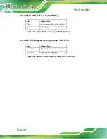
Page 124: ...eep current BIOS setup Default Short Clear BIOS Table 6 31 Clear CMOS Jumper J_CMOS1 Settings 6 3 2 ME RTC Register Setting Jumper ME_RTC1 Pin Description Short 1 2 Save ME RTC registers Default Short 2 3 Clear ME RTC registers Table 6 32 ME RTC Register Jumper ME_RTC1 Settings ...

Page 125: ...PPC FxxC Q370 Page 107 Appendix A A Regulatory Compliance ...

Page 126: ... 53 EU Български Bulgarian IEI Integration Corp декларира че този оборудване е в съответствие със съществените изисквания и другите приложими правила на Директива 2014 53 EU Česky Czech IEI Integration Corp tímto prohlašuje že tento zařízení je ve shodě se základními požadavky a dalšími příslušnými ustanoveními směrnice 2014 53 EU Dansk Danish IEI Integration Corp erklærer herved at følgende udsty...

Page 127: ...em ar to saistītajiem noteikumiem Direktīvas 2014 53 EU Lietuvių Lithuanian IEI Integration Corp deklaruoja kad šis įranga atitinka esminius reikalavimus ir kitas 2014 53 EU Direktyvos nuostatas Nederlands Dutch IEI Integration Corp dat het toestel toestel in overeenstemming is met de essentiële eisen en de andere relevante bepalingen van richtlijn 2014 53 EU Malti Maltese IEI Integration Corp jid...

Page 128: ...rektive 2014 53 EU Slovensky Slovak IEI Integration Corp týmto vyhlasuje že zariadenia spĺňa základné požiadavky a všetky príslušné ustanovenia Smernice 2014 53 EU Suomi Finnish IEI Integration Corp vakuuttaa täten että laitteet on direktiivin 2014 53 EU oleellisten vaatimusten ja sitä koskevien direktiivin muiden ehtojen mukainen Svenska Swedish IEI Integration Corp förklarar att denna utrustning...

Page 129: ...rence at his own expense Federal Communication Commission Interference Statement This equipment has been assembled with components that comply with the limits for a Class B digital device pursuant to Part 15 of the FCC Rules These limits are designed to provide reasonable protection against harmful interference in a residential installation This equipment generates uses and can radiate radio frequ...

Page 130: ...PPC FxxC Q370 Page 112 B Safety Precautions Appendix B ...

Page 131: ...e risk of electric shock make sure power cord is unplugged from wall socket To fully disengage the power to the unit please disconnect the power cord from the power outlet Refer servicing to qualified service personnel The power outlet shall be readily available and accessible Do not apply voltage levels that exceed the specified voltage range Doing so may cause fire and or an electrical shock Use...

Page 132: ... susceptible to ESD It is therefore critical that whenever the PPC FxxC Q370 is opened and any of the electrical components are handled the following anti static precautions are strictly adhered to Wear an anti static wristband Wearing a simple anti static wristband can help to prevent ESD from damaging any electrical component Self grounding Before handling any electrical component touch any grou...

Page 133: ...classified as electronic device in terms of the European Directive 2012 19 EU WEEE and must not be disposed of as domestic garbage EU wide legislation as implemented in each Member State requires that waste electrical and electronic products carrying the mark left must be disposed of separately from normal household waste This includes monitors and electrical accessories such as signal cables or p...

Page 134: ...anel PC gently wipe it with a piece of soft dry cloth or a slightly moistened cloth The interior of the device does not require cleaning Keep fluids away from the device interior Be cautious of all small removable components when vacuuming the device Never drop any objects or liquids through the openings of the device Be cautious of any possible allergic reactions to solvents or chemicals used whe...

Page 135: ... plastic parts Vacuum cleaner Using a vacuum specifically designed for computers is one of the best methods of cleaning the device Dust and dirt can restrict the airflow in the device and cause its circuitry to corrode Cotton swabs Cotton swaps moistened with rubbing alcohol or water are excellent tools for wiping hard to reach areas Foam swabs Whenever possible it is best to use lint free swabs s...

Page 136: ...PPC FxxC Q370 Page 118 Appendix C C BIOS Menu Options ...

Page 137: ...C Health Status 56 CPU_FAN1 Smart Fan Control SYS_FAN Smart Fan Control Auto Mode 58 Auto mode fan start temperature 58 Auto mode fan off temperature 58 Auto mode fan start PWM 58 Auto mode fan slope PWM 58 Case Open Beep Disabled 59 Serial Port Enabled 60 Wake system with Fixed Time Disabled 61 Console Redirection Disabled 63 Terminal Type ANSI 63 Bits per second 115200 63 Data Bits 8 63 Parity N...

Page 138: ...DUAL 77 USB Power SW2 5V DUAL 77 PCIEX4_1 Slot Enabled 79 PCIEX4_2 Slot Enabled 79 M2_M1 Slot Enabled 80 M2_M2 Slot Enabled 80 PCIe Speed Auto 80 SATA Controller s Enabled 81 SATA Mode Selection AHCI 82 Hot Plug 82 HD Audio Enabled 83 Administrator Password 84 User Password 84 Bootup NumLock State On 85 Quiet Boot Enabled 86 UEFI Boot Disabled 86 Launch PXE OpROM Disabled 86 Option ROM Messages Fo...

Page 139: ...PPC FxxC Q370 Page 121 Appendix D D Watchdog Timer ...

Page 140: ...function call INT 15H is used to control the Watchdog Timer INT 15H AH 6FH Sub function AL 2 Sets the Watchdog Timer s period BL Time out value Its unit second is dependent on the item Watchdog Timer unit select in CMOS setup Table D 1 AH 6FH Sub function Call sub function 2 to set the time out period of Watchdog Timer first If the time out value is not zero the Watchdog Timer starts counting down...

Page 141: ...tem resets Example program INITIAL TIMER PERIOD COUNTER W_LOOP MOV AX 6F02H setting the time out value MOV BL 30 time out value is 48 seconds INT 15H ADD THE APPLICATION PROGRAM HERE CMP EXIT_AP 1 is the application over JNE W_LOOP No restart the application MOV AX 6F02H disable Watchdog Timer MOV BL 0 INT 15H EXIT ...

Page 142: ...PPC FxxC Q370 Page 124 Appendix E E Error Beep Code ...

Page 143: ...found 4 Recovery failed 4 S3 Resume failed 7 Reset PPI is not available E 2 DXE Beep Codes Number of Beeps Description 1 Invalid password 4 Some of the Architectural Protocols are not available 5 No Console Output Devices are found 5 No Console Input Devices are found 6 Flash update is failed 7 Reset protocol is not available 8 Platform PCI resource requirements cannot be met NOTE If you have any ...

Page 144: ...PPC FxxC Q370 Page 126 Appendix F F Hazardous Materials Disclosure ...

Page 145: ...olybrominated Diphenyl Ethers PBDE Bis 2 ethylhexyl phthalate DEHP Butyl benzyl phthalate BBP Dibutyl phthalate DBP Diisobutyl phthalate DIBP Housing O O O O O O O O O O Printed Circuit Board O O O O O O O O O O Metal Fasteners O O O O O O O O O O Cable Assembly O O O O O O O O O O Fan Assembly O O O O O O O O O O Power Supply Assemblies O O O O O O O O O O Battery O O O O O O O O O O O This toxic...

Page 146: ...的环境友好使用期限的可替换元件 像是电池或灯管 这些 元件将会单独标示出来 部件名称 有毒有害物质或元素 铅 Pb 汞 Hg 镉 Cd 六价铬 CR VI 多溴联苯 PBB 多溴二苯醚 PBDE 壳体 O O O O O O 印刷电路板 O O O O O O 金属螺帽 O O O O O O 电缆组装 O O O O O O 风扇组装 O O O O O O 电力供应组装 O O O O O O 电池 O O O O O O O 表示该有毒有害物质在该部件所有物质材料中的含量均在SJ T11364 2014與GB T26572 2011 标准规定的限量要求以下 X 表示该有毒有害物质至少在该部件的某一均质材料中的含量超出 SJ T11364 2014 與 GB T26572 2011 标准规定的限量要求 ...

Reviews: