PPC-FxxD-ULT5
Page 37
Ensure that all four of the mounting screws fit snuggly into their respective
slotted holes.
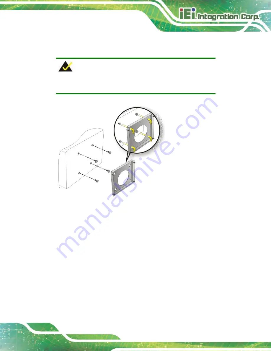
NOTE:
In the diagram below the bracket is already installed on the wall.
Figure 3-29: Mount the Chassis
Step 9:
Secure the panel PC with the wall-mounting kit. To do this, stick the protective
cushion to the wall-mounting kit first. Then, put the wall-mounting kit on the top
panel of the panel PC. Carefully mark the location of the wall-mounting kit screw
holes on the wall. Drill a pilot hole at the marked location on the wall. Secure the
wall-mounting kit to the wall by inserting a retention screw into the pilot hole on
the wall (Figure 3-30). This step is to avoid the panel PC being pushed apart
from the wall-mounting bracket accidentally.
S
te
p
0
:
Summary of Contents for PPC-F D-ULT5 Series
Page 2: ...PPC FxxD ULT5 Page ii Revision Date Version Changes December 1 2020 1 00 Initial release ...
Page 15: ...PPC FxxD ULT5 Page 1 Chapter 1 1 Introduction ...
Page 28: ...PPC FxxD ULT5 Page 14 Chapter 2 2 Unpacking ...
Page 31: ...PPC FxxD ULT5 Page 17 Chapter 3 3 Installation ...
Page 47: ...PPC FxxD ULT5 Page 33 Figure 3 24 Tighten the Mounting Clamp Screws ...
Page 59: ...PPC FxxD ULT5 Page 45 Chapter 4 4 BIOS ...
Page 94: ...PPC FxxD ULT5 Page 80 5 Interface Connectors Chapter 5 ...
Page 108: ...PPC FxxD ULT5 Page 94 Appendix A A Regulatory Compliance ...
Page 113: ...PPC FxxD ULT5 Page 99 B Safety Precautions Appendix B ...
Page 119: ...PPC FxxD ULT5 Page 105 Appendix C C BIOS Menu Options ...
Page 122: ...PPC FxxD ULT5 Page 108 Appendix D D Watchdog Timer ...
Page 125: ...PPC FxxD ULT5 Page 111 Appendix E E Error Beep Code ...
Page 127: ...PPC FxxD ULT5 Page 113 Appendix F F Hazardous Materials Disclosure ...


