PPC-FxxD-ULT5
Page 81
5.1 Peripheral Interface Connectors
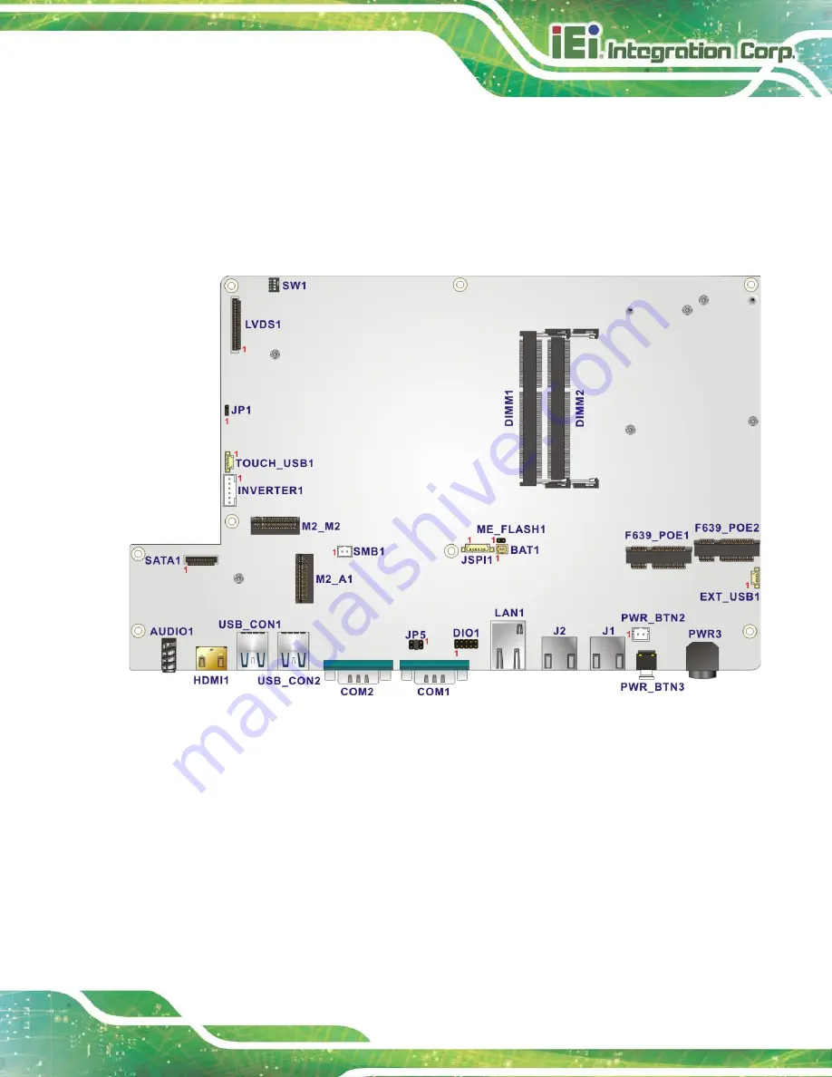
The PPC-FxxD-ULT5 panel PC motherboard comes with a number of peripheral interface
connectors and configuration jumpers. The connector locations are shown in
The Pin 1 locations of the on-board connectors are also indicated in the diagram below.
The connector pinouts for these connectors are listed in the following sections.
Figure 5-1: Main Board Layout Diagram
Summary of Contents for PPC-F D-ULT5 Series
Page 2: ...PPC FxxD ULT5 Page ii Revision Date Version Changes December 1 2020 1 00 Initial release ...
Page 15: ...PPC FxxD ULT5 Page 1 Chapter 1 1 Introduction ...
Page 28: ...PPC FxxD ULT5 Page 14 Chapter 2 2 Unpacking ...
Page 31: ...PPC FxxD ULT5 Page 17 Chapter 3 3 Installation ...
Page 47: ...PPC FxxD ULT5 Page 33 Figure 3 24 Tighten the Mounting Clamp Screws ...
Page 59: ...PPC FxxD ULT5 Page 45 Chapter 4 4 BIOS ...
Page 94: ...PPC FxxD ULT5 Page 80 5 Interface Connectors Chapter 5 ...
Page 108: ...PPC FxxD ULT5 Page 94 Appendix A A Regulatory Compliance ...
Page 113: ...PPC FxxD ULT5 Page 99 B Safety Precautions Appendix B ...
Page 119: ...PPC FxxD ULT5 Page 105 Appendix C C BIOS Menu Options ...
Page 122: ...PPC FxxD ULT5 Page 108 Appendix D D Watchdog Timer ...
Page 125: ...PPC FxxD ULT5 Page 111 Appendix E E Error Beep Code ...
Page 127: ...PPC FxxD ULT5 Page 113 Appendix F F Hazardous Materials Disclosure ...


