PPC-F08B/F10B-BT Panel PC
Page 19
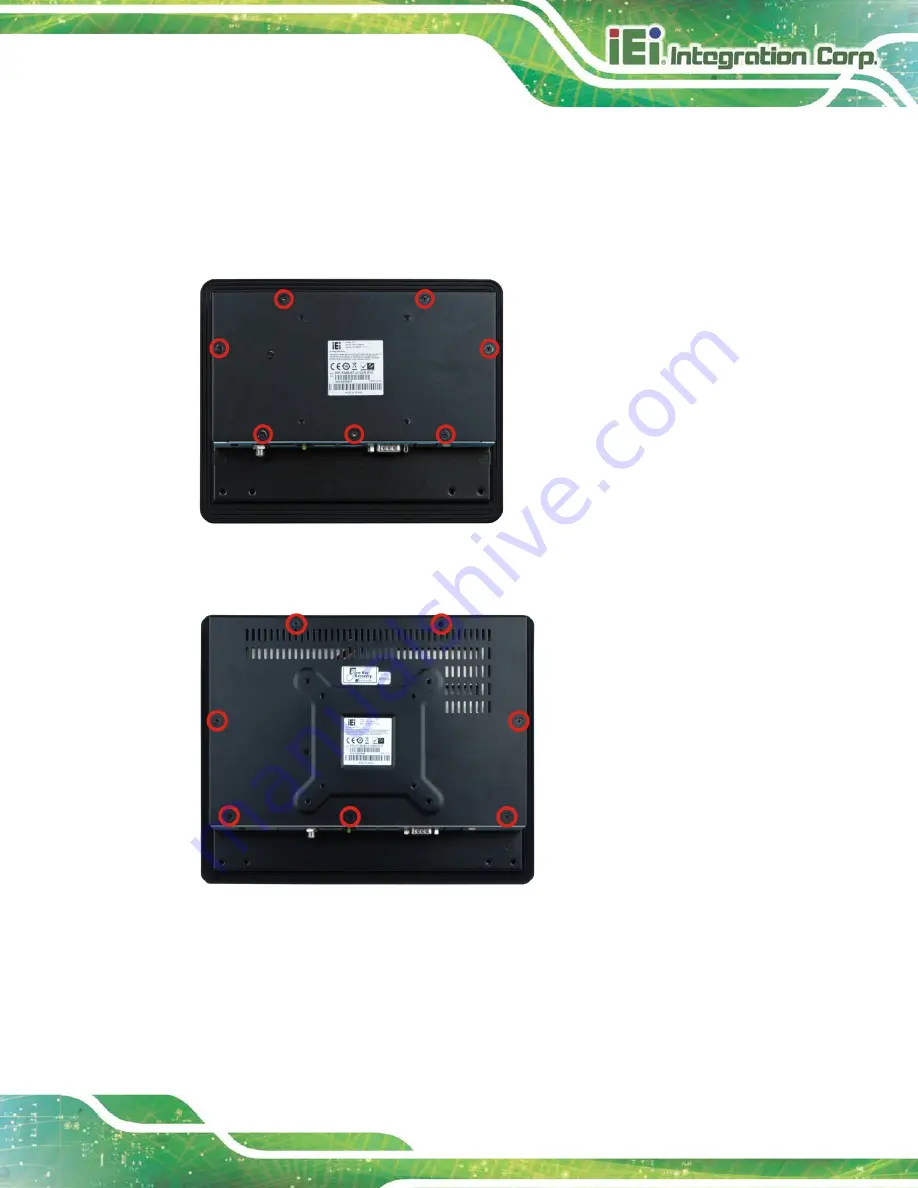
3.5 Removing the Back Cover
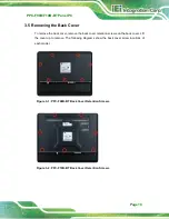
To remove the back cover, remove the back cover retention screws on the back cover. Lift
the cover up to remove. The following diagrams show the back cover screw locations of
each model.
Figure 3-1: PPC-F08B-BT Back Cover Retention Screws
Figure 3-2: PPC-F10B-BT Back Cover Retention Screws
Summary of Contents for PPC-F08B
Page 14: ......
Page 15: ...PPC F08B F10B BT Panel PC Page 1 1 Introduction Chapter 1...
Page 25: ...PPC F08B F10B BT Panel PC Page 11 2 Unpacking Chapter 2...
Page 30: ...PPC F08B F10B BT Panel PC Page 16 3 Installation Chapter 3...
Page 60: ...PPC F08B F10B BT Panel PC Page 46 Chapter 4 4 System Maintenance...
Page 64: ...PPC F08B F10B BT Panel PC Page 50 5 BIOS Setup Chapter 5...
Page 97: ...PPC F08B F10B BT Panel PC Page 83 6 Interface Connectors Chapter 6...
Page 112: ...PPC F08B F10B BT Panel PC Page 98 Appendix A A Regulatory Compliance...
Page 118: ...PPC F08B F10B BT Panel PC Page 104 B BIOS Configuration Options Appendix B...
Page 121: ...PPC F08B F10B BT Panel PC Page 107 C Safety Precautions Appendix C...
Page 127: ...PPC F08B F10B BT Panel PC Page 113 D Watchdog Timer Appendix D...
Page 130: ...PPC F08B F10B BT Panel PC Page 116 Appendix E E Hazardous Materials Disclosure...


