PPC-F08B/F10B-BT Panel PC
Page 29
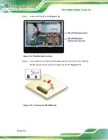
Figure 3-16: COM2 Serial Port Pin 9 Setting Jumper Location
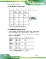
3.9.4 RS-232 Serial Port Pinouts
The pinouts of the RS-232 serial port (COM1) are listed in the following table.
Pin No. Description
Pin No.
Description
1
DCD
2
RXD
3
TXD
4
DTR
5
GND
6
DSR
7
RTS
8
CTS
9
RI
Table 3-4: RS-232 Serial Port (COM1) Pinouts
3.9.5 RS-232 Serial Port Connection
The RS-232 port (COM1) is a RJ-45 serial device connector on the bottom panel. The
COM1 port connects to a cable with a standard D-sub 9 connector at the other end (cables
included). Follow the steps below to connect a serial device to the PPC-F08B/F10B-BT
panel PC.
Summary of Contents for PPC-F08B
Page 14: ......
Page 15: ...PPC F08B F10B BT Panel PC Page 1 1 Introduction Chapter 1...
Page 25: ...PPC F08B F10B BT Panel PC Page 11 2 Unpacking Chapter 2...
Page 30: ...PPC F08B F10B BT Panel PC Page 16 3 Installation Chapter 3...
Page 60: ...PPC F08B F10B BT Panel PC Page 46 Chapter 4 4 System Maintenance...
Page 64: ...PPC F08B F10B BT Panel PC Page 50 5 BIOS Setup Chapter 5...
Page 97: ...PPC F08B F10B BT Panel PC Page 83 6 Interface Connectors Chapter 6...
Page 112: ...PPC F08B F10B BT Panel PC Page 98 Appendix A A Regulatory Compliance...
Page 118: ...PPC F08B F10B BT Panel PC Page 104 B BIOS Configuration Options Appendix B...
Page 121: ...PPC F08B F10B BT Panel PC Page 107 C Safety Precautions Appendix C...
Page 127: ...PPC F08B F10B BT Panel PC Page 113 D Watchdog Timer Appendix D...
Page 130: ...PPC F08B F10B BT Panel PC Page 116 Appendix E E Hazardous Materials Disclosure...

