PPC-F12B/15B/17B-BTi Panel PC
Page 43
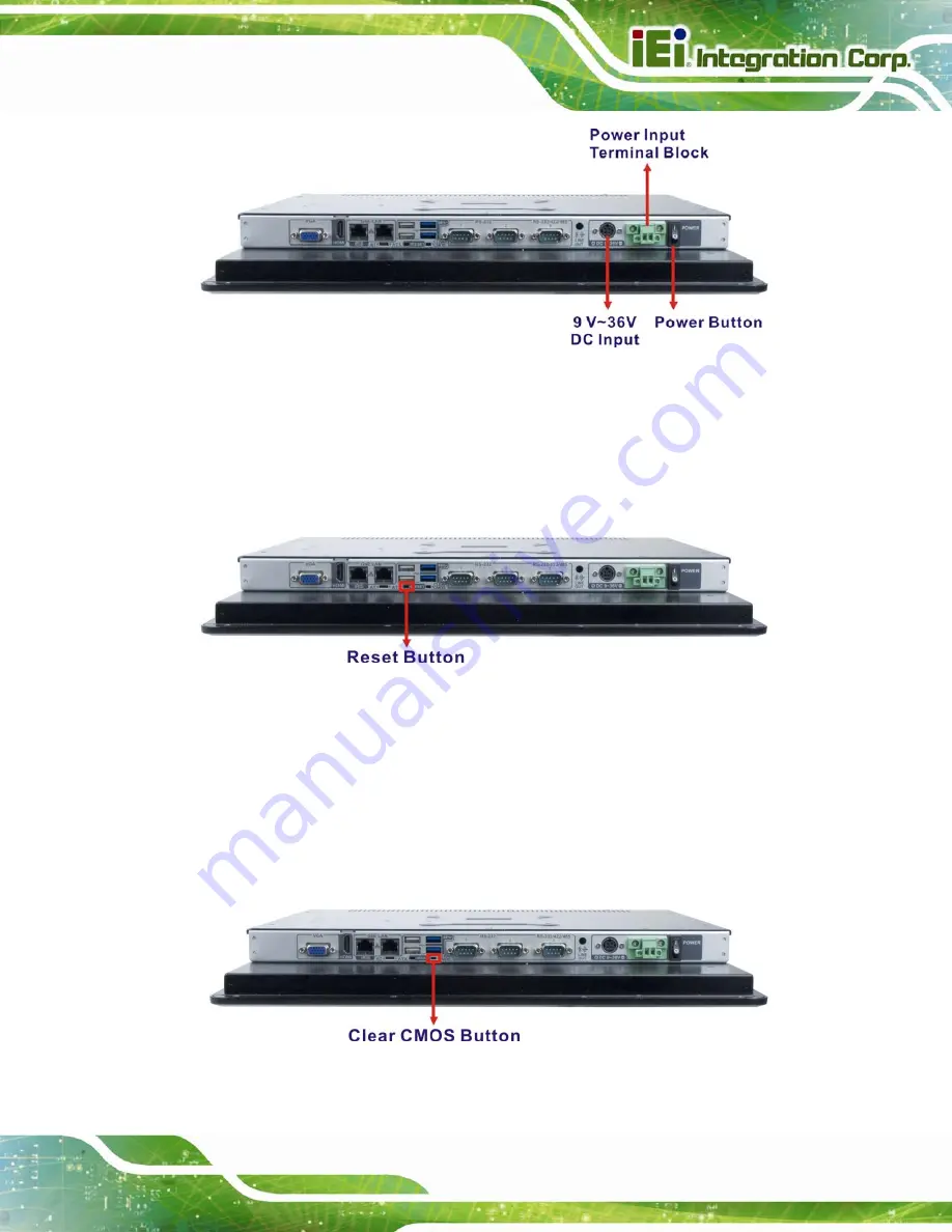
Figure 3-32: Power Connectors and Power Button
3.14 Reset the System
The reset button enables users to reboot the system when the system is turned on. The
reset button location is shown in
. Press the reset button to reboot the system.
Figure 3-33: Reset Button Location
3.15 Clear CMOS
If the PPC-F12B/15B/17B-BTi fails to boot due to improper BIOS settings, the clear CMOS
button clears the CMOS data and resets the system BIOS information. To do this, push
the clear CMOS button for three seconds, and then restart the system. The clear CMOS
button location is shown in
.
Figure 3-34: Clear CMOS Button Location
Summary of Contents for PPC-F12B-BTi
Page 14: ......
Page 15: ...PPC F12B 15B 17B BTi Panel PC Page 1 1 Introduction Chapter 1...
Page 20: ...PPC F12B 15B 17B BTi Panel PC Page 6 Figure 1 5 PPC F15B F17B BTi Bottom View...
Page 26: ...PPC F12B 15B 17B BTi Panel PC Page 12 2 Unpacking Chapter 2...
Page 30: ...PPC F12B 15B 17B BTi Panel PC Page 16 3 Installation Chapter 3...
Page 62: ...PPC F12B 15B 17B BTi Panel PC Page 48 Chapter 4 4 System Maintenance...
Page 64: ...PPC F12B 15B 17B BTi Panel PC Page 50 5 BIOS Setup Chapter 5...
Page 101: ...PPC F12B 15B 17B BTi Panel PC Page 87 6 Interface Connectors Chapter 6...
Page 121: ...PPC F12B 15B 17B BTi Panel PC Page 107 Appendix A A Regulatory Compliance...
Page 126: ...PPC F12B 15B 17B BTi Panel PC Page 112 B BIOS Configuration Options Appendix B...
Page 129: ...PPC F12B 15B 17B BTi Panel PC Page 115 C Safety Precautions Appendix C...
Page 134: ...PPC F12B 15B 17B BTi Panel PC Page 120 D Watchdog Timer Appendix D...
Page 137: ...PPC F12B 15B 17B BTi Panel PC Page 123 E Hazardous Materials Disclosure Appendix E...


