PPC-FxxA-H81 Panel PC
Page 133
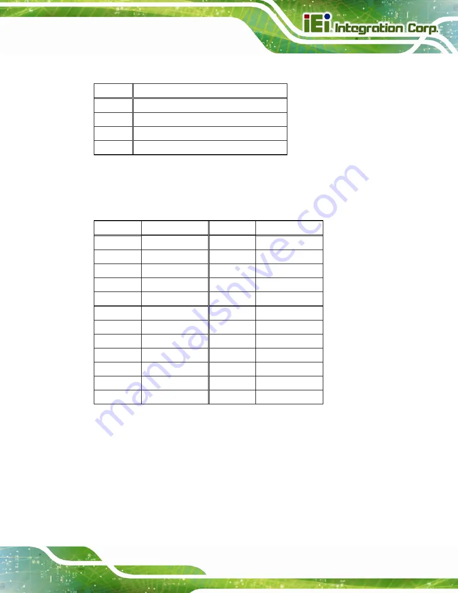
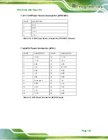
7.2.1 +12V Power Source Connector (CPU12V1)
7.2.2 ATX Power Connector (ATX1)
PIN NO.
DESCRIPTION
PIN NO.
DESCRIPTION
1 +3.3V 13
+3.3V
2 +3.3V 14
-12V
3 GND
15
GND
4 +5V
16
PS_ON
5 GND
17
GND
6 +5V
18
GND
7 GND
19
GND
8 Power
good
20
-5V
9 5VSB
21
+5V
10 +12V
22 +5V
11 +12V
23 +5V
12 +3.3V
24 GND
PIN NO.
DESCRIPTION
1 GND
2 GND
3 +12V
4 +12V
Table 7-2: +12V Power Source Connector ( CPU12V1) Pinouts
Table 7-3: ATX Power Connector (ATX1) Pinouts
Summary of Contents for PPC-FxxA-H81
Page 14: ...PPC FxxA H81 Panel PC Page 1 1 Introduction Chapter 1 ...
Page 20: ...PPC FxxA H81 Panel PC Page 7 Figure 1 4 Bottom View ...
Page 28: ...PPC FxxA H81 Panel PC Page 15 2 Unpacking Chapter 2 ...
Page 32: ...PPC FxxA H81 Panel PC Page 19 3 Installation Chapter 3 ...
Page 69: ...PPC FxxA H81 Panel PC Page 56 Chapter 4 4 System Maintenance ...
Page 75: ...PPC FxxA H81 Panel PC Page 62 5 BIOS Setup Chapter 5 ...
Page 113: ...PPC FxxA H81 Panel PC Page 100 6 Driver Installation Chapter 6 ...
Page 142: ...PPC FxxA H81 Panel PC Page 129 7 Interface Connectors Chapter 7 ...
Page 162: ...PPC FxxA H81 Panel PC Page 149 A BIOS Configuration Options Appendix A ...
Page 165: ...PPC FxxA H81 Panel PC Page 152 B Safety Precautions Appendix B ...
Page 170: ...PPC FxxA H81 Panel PC Page 157 C Watchdog Timer Appendix C ...
Page 173: ...PPC FxxA H81 Panel PC Page 160 D Hazardous Materials Disclosure Appendix D ...


