PPC-FxxA-H81 Panel PC
Page 136
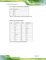
7.2.7 Front Panel Connector (F_PANEL1)
FUCNTION
PIN NO.
DESCRIPTION
FUCNTION
PIN NO.
DESCRIPTION
1
+5V
2
BEEP_PWR
3
NC
4
NC
Power LED
5
GND
6
NC
7
PWRBTN_SW#
Speaker
8
PC_BEEP
Power Button
9
GND
10
NC
11
+5V
12
EXTRST-
HDD LED
13
SATA_LED#
Reset
14
GND
7.2.8 I
2
C Connector (CN5)
7.2.9 IPMI Active LED Connector (LEDCN1)
Table 7-8: Front Panel Connector (F_PANEL1) Pinouts
PIN NO.
DESCRIPTION
1 GND
2 PCH_GP38
3 PCH_GP39
4 +5V
Table 7-9: I
2
C Connector (CN5) Pinouts
PIN NO.
DESCRIPTION
1
I
2
IPMI_LED-
Table 7-10: IPMI Active LED Connector (LEDCN1) Pinouts
Summary of Contents for PPC-FxxA-H81
Page 14: ...PPC FxxA H81 Panel PC Page 1 1 Introduction Chapter 1 ...
Page 20: ...PPC FxxA H81 Panel PC Page 7 Figure 1 4 Bottom View ...
Page 28: ...PPC FxxA H81 Panel PC Page 15 2 Unpacking Chapter 2 ...
Page 32: ...PPC FxxA H81 Panel PC Page 19 3 Installation Chapter 3 ...
Page 69: ...PPC FxxA H81 Panel PC Page 56 Chapter 4 4 System Maintenance ...
Page 75: ...PPC FxxA H81 Panel PC Page 62 5 BIOS Setup Chapter 5 ...
Page 113: ...PPC FxxA H81 Panel PC Page 100 6 Driver Installation Chapter 6 ...
Page 142: ...PPC FxxA H81 Panel PC Page 129 7 Interface Connectors Chapter 7 ...
Page 162: ...PPC FxxA H81 Panel PC Page 149 A BIOS Configuration Options Appendix A ...
Page 165: ...PPC FxxA H81 Panel PC Page 152 B Safety Precautions Appendix B ...
Page 170: ...PPC FxxA H81 Panel PC Page 157 C Watchdog Timer Appendix C ...
Page 173: ...PPC FxxA H81 Panel PC Page 160 D Hazardous Materials Disclosure Appendix D ...


