PPC-FxxA-H81 Panel PC
Page 51
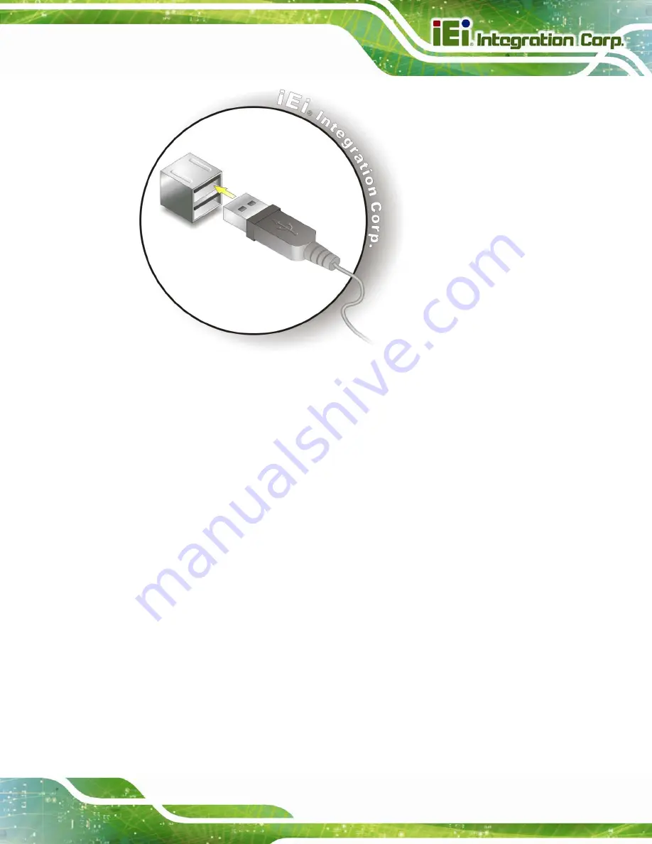
Figure 3-37: USB Device Connection
Step 3:
Insert the device connector
. Once aligned, gently insert the USB device
connector into the onboard connector.
3.11.6 VGA Connector Connection
The VGA connector connects to a monitor that accepts VGA video input. To connect the
PPC-FxxA-H81 to a VGA monitor, follow the steps below,
Step 1:
Locate the female DB-15 connector
. The location of the female DB-15
connector is shown in
7
Figure 1-4
.
Step 2:
Align the VGA connector
. Align the male DB-15 connector on the VGA screen
cable with the female DB-15 connector on the external peripheral interface.
Step 3:
Insert the VGA connector
. Once the connectors are properly aligned, insert the
male connector from the VGA screen into the female connector on the
PPC-FxxA-H81. See
7
Figure 3-38
.
Summary of Contents for PPC-FxxA-H81
Page 14: ...PPC FxxA H81 Panel PC Page 1 1 Introduction Chapter 1 ...
Page 20: ...PPC FxxA H81 Panel PC Page 7 Figure 1 4 Bottom View ...
Page 28: ...PPC FxxA H81 Panel PC Page 15 2 Unpacking Chapter 2 ...
Page 32: ...PPC FxxA H81 Panel PC Page 19 3 Installation Chapter 3 ...
Page 69: ...PPC FxxA H81 Panel PC Page 56 Chapter 4 4 System Maintenance ...
Page 75: ...PPC FxxA H81 Panel PC Page 62 5 BIOS Setup Chapter 5 ...
Page 113: ...PPC FxxA H81 Panel PC Page 100 6 Driver Installation Chapter 6 ...
Page 142: ...PPC FxxA H81 Panel PC Page 129 7 Interface Connectors Chapter 7 ...
Page 162: ...PPC FxxA H81 Panel PC Page 149 A BIOS Configuration Options Appendix A ...
Page 165: ...PPC FxxA H81 Panel PC Page 152 B Safety Precautions Appendix B ...
Page 170: ...PPC FxxA H81 Panel PC Page 157 C Watchdog Timer Appendix C ...
Page 173: ...PPC FxxA H81 Panel PC Page 160 D Hazardous Materials Disclosure Appendix D ...


