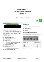
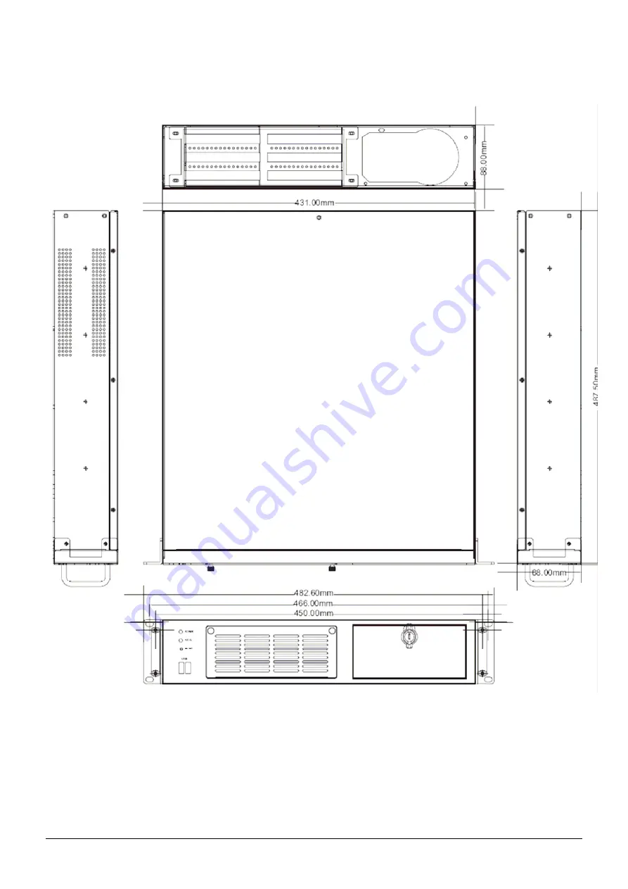
background image

 
RACK-220GATX QIG 

               IEI Technology Corp.                             Page  2


DIMENSION DRAWING 

 
The dimensions of RACK-220GATX


are shown below. 


Figure 1: Dimension Drawing (measurement units: millimeter) 

Summary of Contents for RACK-220GATX

Page 1: ...ccessible FDD floppy disk drive bay o 1 x 3 5 Internal HDD hard disk drive bay Dimensions DxWxH o 487 5mm x 431 0mm x 88 0mm Operating Temperature 0 C 50 C Relative Humidity 10 95 Vibration o 5Hz 17Hz 0 1 double amplitude displacement o 17Hz 640Hz 1 5G acceleration peak to peak Shock 10G acceleration peak to peak Weight Net Gross 8 2kg 12 4kg PACKING LIST When unpacking the chassis make sure the f...

Page 2: ...RACK 220GATX QIG IEI Technology Corp Page 2 DIMENSION DRAWING The dimensions of RACK 220GATX are shown below Figure 1 Dimension Drawing measurement units millimeter ...

Page 3: ...NSTALL THE POWER SUPPLY UNIT PSU Once the top cover has been removed install a user supplied PSU Compatible IEI PSUs are listed in Table 2 on page 4 The PSU is installed at the rear of the chassis and secured to the chassis with four retention screws To install a compatible PSU please follow the steps below Step 1 Correctly position the PSU at the rear of the chassis making sure the power switch a...

Page 4: ...rboard are correctly aligned with their respective preformed spaces on the I O shield Step 5 Make sure the microATX motherboard retention screw holes are properly aligned with the retention screw holes in the base of the chassis Step 6 Insert the retention screws to secure the microATX motherboard to the chassis Step 0 Figure 8 Motherboard Retention Screws STEP 6 PCI PCIe EXPANSION CARD INSTALLATI...

Page 5: ...on screws that attach the internal 3 5 HDD bracket to the base of the chassis Figure 11 Four Internal 3 5 HDD Bracket Retention Screws Step 2 Correctly position the HDD into the bracket Make sure the six retention screw holes in the HDD bracket are all aligned with the retention screw holes in the HDD and that the HDD PCB board is against the bracket surface Step 3 To secure the HDD to the bracket...

Page 6: ...ive bay To install an optical drive in the 5 25 front accessible drive bay please follow the steps below Step 1 Remove the main drive bracket by removing the four retention screws that connect it to the chassis Step 2 Remove the front cover of the 5 25 drive bay by removing the four front cover retention screws two on each side Figure 16 5 25 Optical Drive Bay Front Cover Retention Screws Step 3 C...

Page 7: ...d Step 0 STEP 11 COVER REINSTALLATION After the above procedures have been completed the cover can be reinstalled To do this slide the cover back over the chassis and reinsert the seven previously removed retention screws STEP 12 FRONT HANDLE INSTALLATION Two handles are shipped with the RACK 220GATX chassis The handles are installed on the sides at the front of the chassis Each handle is secured ...

Page 8: ...o open the fan filter cover from the left side of the chassis Figure 21 Loosen the Two Thumbscrews on Fan Filter Cover Step 2 Replace the fan filter pad inside Step 3 Reinstall the fan filter cover and fasten the two previously loosened thumbscrews Step 0 CABINET INSTALLATION Supporting rails rack trays or slide rails can be implemented using the mounting holes on the sides of the chassis The four...

Reviews: