RACK-220GATX QIG
IEI Technology Corp. Page 4
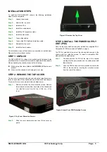
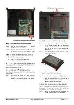
STEP 5: MOTHERBOARD INSTALLATION
To install the motherboard please follow the instructions below.
Step 1:
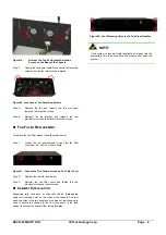
Locate the I/O shield that should have come with the
motherboard. An example of a microATX motherboard
I/O shield was shown below.
Figure 5: Motherboard I/O Shield
Step 2:
Locate the preformed hole reserved for the I/O shield
at the back of the chassis.
Figure 6: Motherboard I/O Shield Location
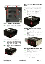
Step 3:
Correctly align the I/O shield with the preformed space
at the back of the chassis. Then, gently push the I/O
shield into the space. The I/O shield should be
securely clipped into the preformed space.
Figure 7: Motherboard I/O Shield Installed
Step 4:
Next, place the motherboard into the chassis. Make
sure that the external peripheral connectors on the
microATX motherboard are correctly aligned with their
respective preformed spaces on the I/O shield.
Step 5:
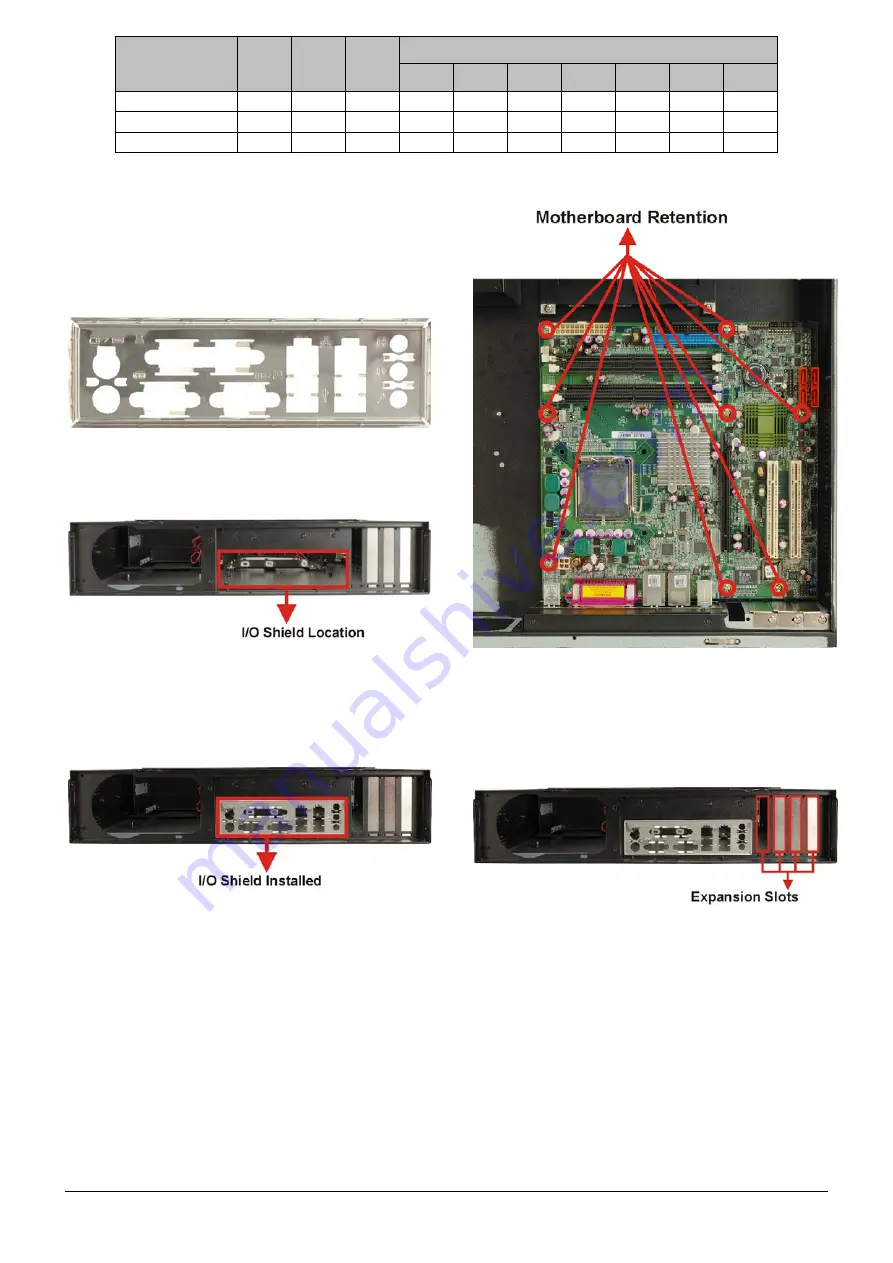
Make sure the microATX motherboard retention screw
holes are properly aligned with the retention screw
holes in the base of the chassis.
Step 6:
Insert the retention screws to secure the microATX
motherboard to the chassis.
Step 0:
Figure 8: Motherboard Retention Screws
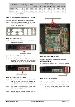
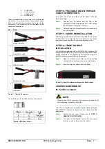
STEP 6: PCI/PCIe EXPANSION CARD
INSTALLATION
The RACK-220GATX supports up to four PCI/PCIe expansion
cards.
Figure 9: PCI/PCIe Expansion Slots
If a PCI expansion card or a PCIe expansion card is being installed
please follow the instructions below.
Step 1:
Remove the slot cover at the back of the backplane
bracket. To do this, remove the slot cover retention
screw on the side of the slot cover.
Output Range
Model No.
Input
Type
Watt
+3.3V
+5V
+12V1 +12V2
-5V
-12V +5Vsb
ACE-832AP-RS
AC ATX
300W 28A 30A 15A N/A 0.3A 0.8A 2A
ACE-841AP-S-RS AC ATX
400W 28A 33A 20A N/A 0.5A 1A 2A
ACE-850AP-RS
AC ATX
500W 27A 29A 18A 18A 0.3A 0.8A 2A
Table 2: Compatible IEI PSUs.