RACK-220GATX QIG
IEI Technology Corp. Page 5
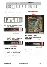
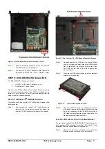
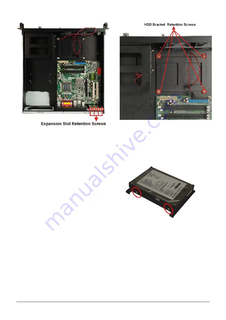
Figure 10: PCI/PCIe Expansion Slot Retention Screws
Step 2:
Slide the PCI/PCIE expansion card into a reserved
PCI/PCIE socket on the backplane.
Step 3:
To secure the PCI/PCIE expansion card, reinsert the
previously removed slot cover retention screw.
Step 0:Step 0:
STEP 8: DISK DRIVES INSTALLATION
The RACK-220GATX chassis can support
o
1 x FDD, 1 x HDD and 1 x optical drive, or
o
2 x HDDs and 1 x optical drive
One 3.5” drive (FDD or HDD) and one optical drive are mounted
into a front accessible bracket. One HDD is installed into an
internal 3.5” drive bracket. To install the drives please follow the
steps outlined in the sections below.
S
TEP
8.1: I
NTERNAL
3.5
"
HDD I
NSTALLATION
To install an HDD in the internal 3.5” HDD bracket, please follow
the steps below.
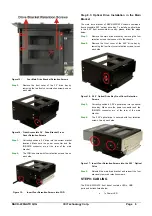
Step 1:
First remove the internal 3.5” HDD bracket by
removing the four retention screws that attach the
internal 3.5” HDD bracket to the base of the chassis.
Figure 11: Four Internal 3.5
"
HDD Bracket Retention Screws
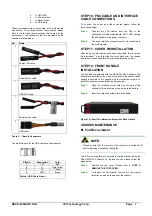
Step 2:
Correctly position the HDD into the bracket. Make
sure the six retention screw holes in the HDD bracket
are all aligned with the retention screw holes in the
HDD, and that the HDD PCB board is against the
bracket surface.
Step 3:
To secure the HDD to the bracket, insert four retention
screws, two on each side.
Figure 12:
Insert HDD Retention Screws
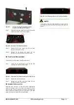
Step 4:
Once the HDD is secured, the HDD bracket can be
reinstalled. Correctly position the bracket making sure
the power connector and the IDE/SATA connector of
HDD face the backplane bracket and reinsert the four
previously removed retention screws.
Step 0:
S
TEP
8.2: FDD I
NSTALLATION IN THE
M
AIN
B
RACKET
The main drive bracket of the RACK-220GATX chassis contains a
front accessible FDD drive bay. To install a FDD in the 3.5” front
accessible drive bay, please follow the steps below:
Step 1:
Remove the main drive bracket by removing the four
retention screws that connect it to the chassis.

