RACK-220GATX QIG
IEI Technology Corp. Page 6
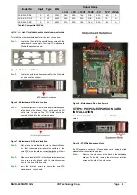
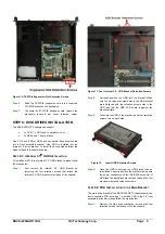
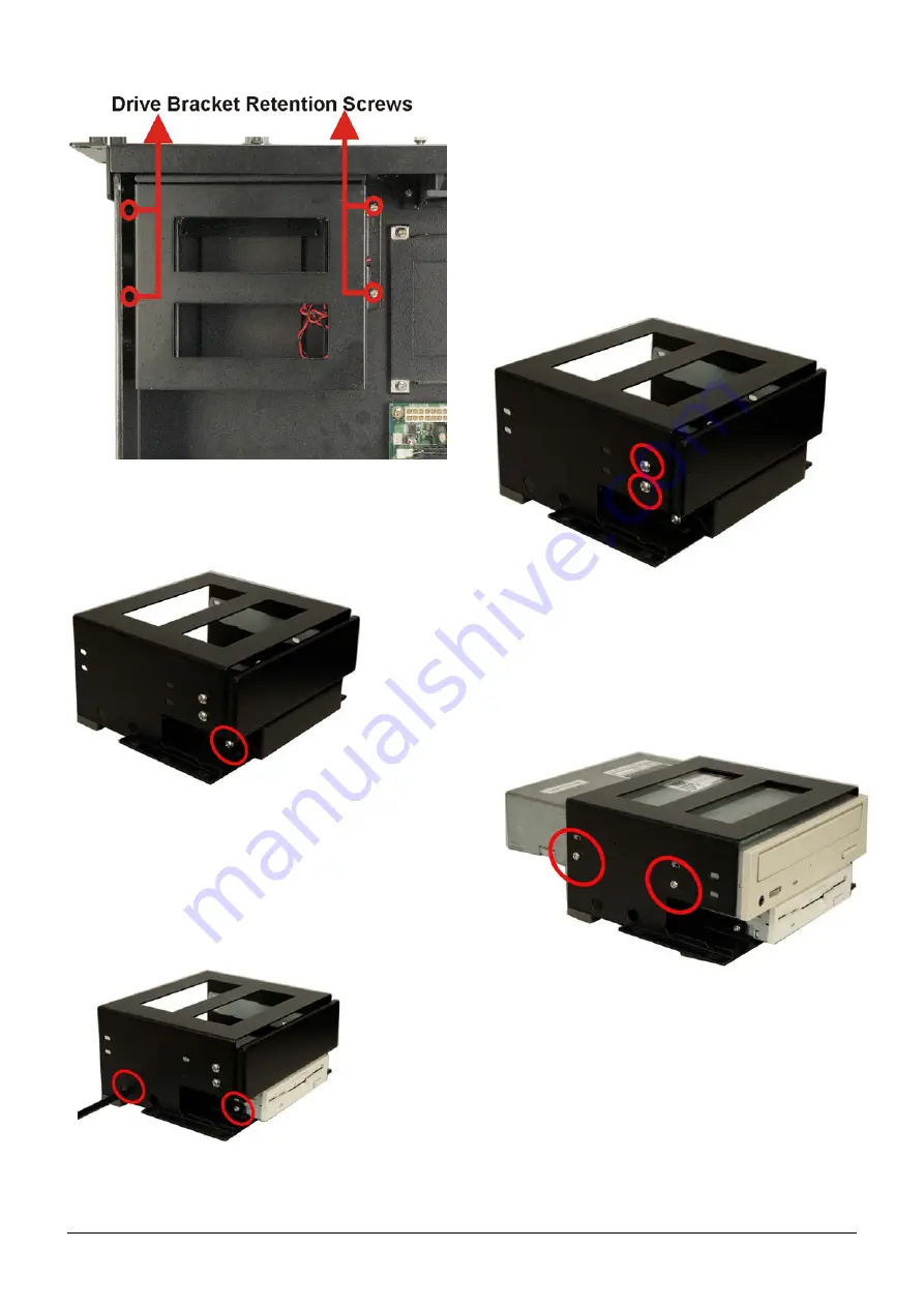
Figure 13:
Four Main Drive Bracket Retention Screws
Step 2:
Remove the front cover of the 3.5” drive bay by
removing the two front cover retention screws, one on
each side.
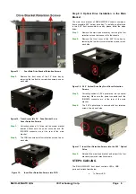
Figure 14: Front Accessible 3.5
"
Drive Bracket Front
Cover Retention Screws
Step 3:
Correctly position a 3.5” drive into the correct bracket
locations. Make sure the power connector and the
IDE/SATA connector are at the rear of the main
bracket.
Step 4:
The FDD is secured with four retention screws, two on
each side.
Step 0:
Figure 15:
Insert Four Retention Screws into FDD
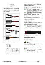
Step 8.3: Optical Drive Installation in the Main
Bracket
The main drive bracket of RACK-220GATX chassis contains a
front accessible 5.25” optical drive bay. To install an optical drive
in the 5.25” front accessible drive bay, please follow the steps
below:
Step 1:
Remove the main drive bracket by removing the four
retention screws that connect it to the chassis.
Step 2:
Remove the front cover of the 5.25” drive bay by
removing the four front cover retention screws, two on
each side.
Figure 16: 5.25
"
Optical Drive Bay Front Cover Retention
Screws
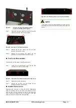
Step 3:
Correctly position a 5.25” optical drive into the optical
drive bay. Make sure the power connector and the
IDE/SATA connector are at the rear of the main
bracket.
Step 4:
The 5.25” optical drive is secured with four retention
screws, two on each side.
Figure 17: Insert Four Retention Screws into the 5.25
"
Optical
Drive
Step 5:
Reinstall the main drive bracket and reinsert the four
previously removed retention screws.
Step 0:
STEP 9: CABLING
The RACK-220GATX front bezel contains LEDs, USB
ports and buttons listed below.
o
1 x Power LED