
RACK-220GATX QIG
IEI Technology Corp. Page 8
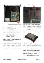
Figure 19:
Remove the Two Fan Bracket Retention
Screws on the Base of the Chassis
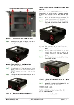
Step 3:
Unplug the fan power cable.Remove two fan retention
screws from the fan that must be replaced.
Figure 20: Locations of Fan Retention Screws
Step 4:
Replace the fan and reinsert the two previously
removed fan retention screws.
Step 5:
Reinstall the fan bracket and reinsert the two
previously removed fan bracket retention screws.
F
AN
F
ILTER
R
EPLACEMENT
To replace the fan filter, please follow the steps below.
.
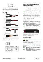
Step 1:
Loosen the two thumbscrews to open the fan filter
cover from the left side of the chassis.
Figure 21: Loosen the Two Thumbscrews on Fan Filter Cover
Step 2:
Replace the fan filter pad inside.
Step 3:
Reinstall the fan filter cover and fasten the two
previously loosened thumbscrews.
Step 0:
C
ABINET
I
NSTALLATION
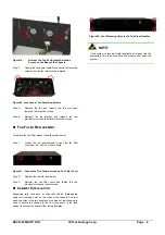
Supporting rails, rack trays, or slide rails can be implemented
using the mounting holes on the sides of the chassis. The four
mounting holes in the two handles on the sides of the chassis are
used to secure the chassis to the front rack posts in the rack
cabinet to prevent the chassis from falling forwards.
Figure 22: Four Mounting Holes in the Two Front Handles
NOTE:
If the system is running critical applications, please find the
appropriate time to backup data and properly shut down the
system.


