RACK-3200G QIG IEI Technology Corp.
Page 6
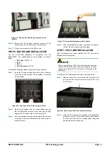
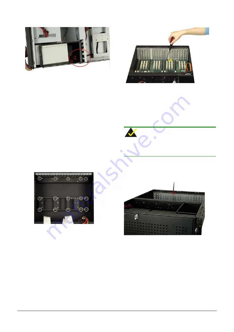
Figure 15: Run the PSU Cables beneath the Center
Divider
Step 12:
Reinsert the PSU bracket retention screws into the
chassis to secure the PSU bracket to the chassis.
Step 13:
Plug the power cable into the PSU socket.
Step 0:
STEP 6: BACKPLANE INSTALLATION
The IEI PCI-19S-RS backplane is compatible with the
RACK-3200G. The specifications of the backplane are shown
below.
o
SBC Type:
PICMG 1.0
o
PCI:
4
o
ISA:
14
o
PSU Connector:
AT/ATX
To install the backplane please follow the instructions below.
Step 1:
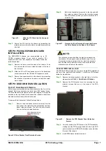
Insert the 15 copper pillars that came with your chassis
at the rear of the chassis. The backplane is mounted
onto the pillars.
Figure 16: Locations of the Fifteen Copper Pillars
Step 2:
Mount the backplane onto the copper pillars ensuring
that the backplane retention screw holes are properly
aligned with the screw holes in the copper pillars.
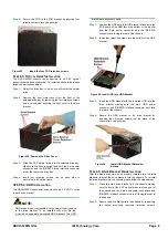
Step 3:
Once the backplane is properly aligned with the retention
screw holes, secure the backplane to the chassis with 15
retention screws.
Figure 17: Secure the Backplane to the Chassis
Step 4:
After the backplane has been secured to the chassis,
connect the power cable to the backplane.
Step 0:
STEP 7: CPU CARD INSTALLATION
After the backplane has been installed, the CPU card can be
installed onto the backplane.
NOTE:
Before you install your CPU card into the chassis, make sure
that the CPU card has been properly configured as it will be
difficult to configure the CPU card when it is installed on the
backplane.
To install the CPU card please follow the instructions below.
Step 1:
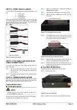
Remove the slot cover at the back of the chassis. To do
this, remove the slot cover retention screw at the top of
the slot cover.
Figure 18: Remove the Slot Cover Retention Screw
Step 2:
Slide the CPU card into the sockets on the backplane
reserved for the CPU card. Make sure the back edge of
the CPU card slots into the corresponding card guide
located behind the cooling fans.


