RACK-360G QIG IEI Integration Corp. Page 7
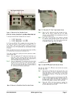
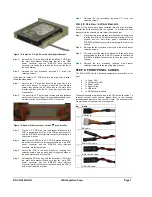
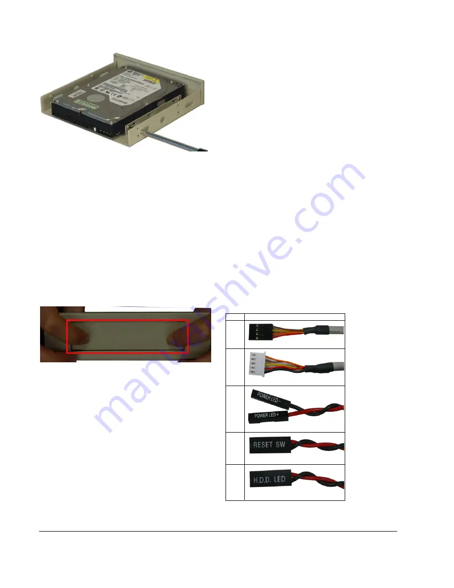
Figure 15: Install a 3.5” Disk Drive into the Adapter Bracket
Step 4:
Reinsert the 3.5” drive tray, with the installed 3.5” HDD into
the main drive bracket. Make sure that the 4-pin HDD
power connector and the IDE/SATA drive interface
connector are facing the rear and the drive is at the top of
the drive bracket.
Step 5:
Reinsert the four previously removed 3.5” drive tray
retention screws.
Step 0:
If you want to install a 3.5” FDD drive into the main drive bracket,
follow the steps below:
Step 1:
Remove the 3.5” drive tray from the top drive bay in the
main drive bracket. To do this, remove the four retention
screws that secure the 3.5” drive tray to the main drive
bracket and then slide the 3.5” drive tray out of the main
drive bracket.
Step 2:
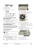
The front of the 3.5” drive tray is covered with a detachable
metal cover. Use your fingers to push the detachable cover
inwards until the cover snaps off the 3.5” drive tray.
Figure 16: Bend off the front cover of the 3.5
"
drive bracket
Step 3:
Place a 3.5” FDD drive into the bracket. Make sure the
FDD is upright and both the 4-pin FDD power connector
and the IDE/SATA drive interface connector are facing the
rear of the bracket.
Step 4:
Make sure the PCB on the 3.5” FDD is placed directly on
the bottom surface of the drive bracket and the 4-pin FDD
power connector and the IDE/SATA drive interface
connector are facing the rear.
Step 5:
Secure the FDD to the drive bracket by inserting four
retention screws (two on each side) through the sides of
the drive bracket and into the HDD.
Step 6:
Reinsert the 3.5” drive tray, with the installed 3.5” FDD into
the main drive bracket. Make sure that the 4-pin FDD
power connector and the IDE/SATA drive interface
connector are facing the rear of the chassis and the FDD is
at the top of the drive bracket.
Step 7:
Reinsert the four previously removed 3.5” drive tray
retention screws.
Step 0:
S
TEP
8.5:
R
EINSTALL THE
D
RIVE
B
RACKETS
Once all the drives have been installed into the drive brackets,
reinstall the drive brackets into the chassis. To reinstall the drive
brackets into the chassis, please follow the steps below:
Step 1:
Place the main drive bracket into the chassis making sure
that the front of the 5.25” optical drives are facing out of the
chassis and the 4-pin drive power connectors and
IDE/SATA interface connectors are all facing the rear of the
chassis.
Step 2:
Reinsert the four, previously removed, main drive bracket
retention screws.
Step 3:
Correctly mount the side drive bracket onto the main drive
bracket making sure the 4-pin FDD power connector and
IDE/SATA interface connector both face the rear of the
chassis.
Step 4:
Reinsert the two, previously removed, side bracket
retention screws into the top of the side bracket.
Step 0:
STEP 9: FRONT PANEL CABLES
The RACK-360G has the following components accessible at the
front:
o
1 x Power LED
o
1 x HDD activity LED
o
1 x Power switch
o
1 x Reset button
o
2 x USB ports
o
1 x PS/2 keyboard/mouse
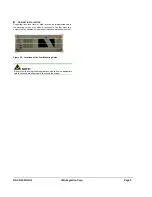
These components are all connected to the CPU card with cables. To
correctly connect these cables, please refer to the technical
documentation that came with your CPU card. The connectors that
are provided with the chassis are listed below:
No. Name
2
USB cable
1
KB cable
1
Power LED cable
1
Reset Switch cable
1
HDD LED cable


