RPC-6010G Rackmount LCD Workstation
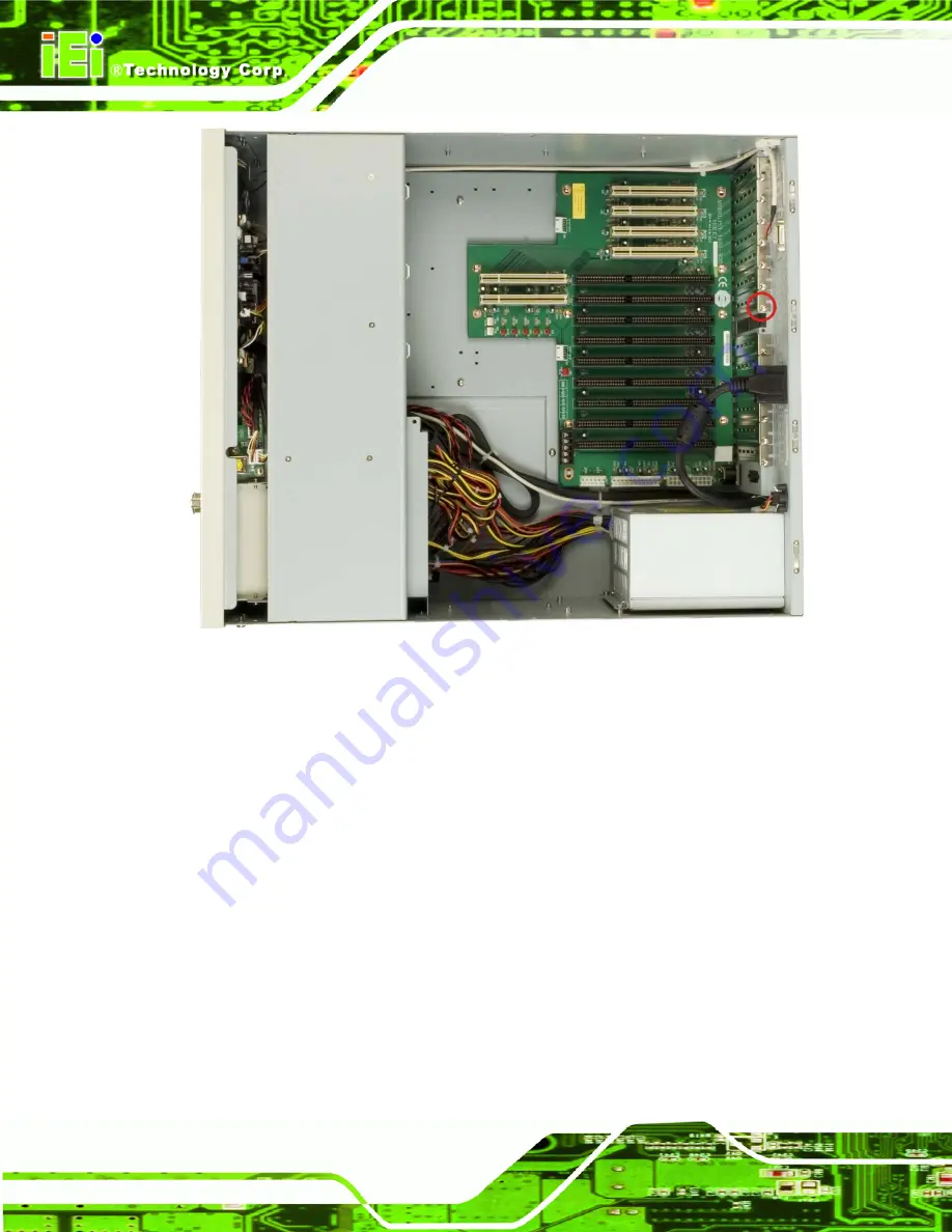
Figure 4-13: Slot Cover Retention Screw
Step 2:
Step 3:
Step 4:
Remove the CPU card clamp. (See
Section 4.5.2
)
Remove the dual CPU card clamp and drive bay stabilizer bracket. (See
Section 4.5.3
)
Slide the CPU card into the reserved PCI/ISA socket on the backplane. Make
sure the back edge of the CPU card slides into the plastic guide rails at the front
end of the chassis.
Page 36
Summary of Contents for RPC-6010G
Page 1: ...RPC 6010G Rackmount LCD Workstation Page i ...
Page 11: ...RPC 6010G Rackmount LCD Workstation 1 Introduction Chapter 1 Page 1 ...
Page 14: ...RPC 6010G Rackmount LCD Workstation THIS PAGE IS INTENTIONALLY LEFT BLANK Page 4 ...
Page 15: ...RPC 6010G Rackmount LCD Workstation 2 Mechanical Overview Chapter 2 Page 5 ...
Page 22: ...RPC 6010G Rackmount LCD Workstation THIS PAGE IS INTENTIONALLY LEFT BLANK Page 12 ...
Page 23: ...RPC 6010G Rackmount LCD Workstation 3 Detailed Specifications Chapter 3 Page 13 ...
Page 27: ...RPC 6010G Rackmount LCD Workstation 4 Installation Chapter 4 Page 17 ...
Page 57: ...RPC 6010G Rackmount LCD Workstation 5 Maintenance Chapter 5 Page 47 ...
Page 69: ...RPC 6010G Rackmount LCD Workstation 6 On Screen Display OSD Controls Chapter 6 Page 59 ...
Page 79: ...RPC 6010G Rackmount LCD Workstation Chapter 7 7 Software Driver Page 69 ...
Page 90: ...RPC 6010G Rackmount LCD Workstation THIS PAGE IS INTENTIONALLY LEFT BLANK Page 80 ...
Page 91: ...RPC 6010G Rackmount LCD Workstation A Certifications Appendix A Page 81 ...
Page 96: ...RPC 6010G Rackmount LCD Workstation THIS PAGE IS INTENTIONALLY LEFT BLANK Page 86 ...
Page 97: ...RPC 6010G Rackmount LCD Workstation C Index Page 87 ...


