S19A/S24A-QM87i Marine Panel PC
Page 27
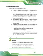
Figure 3-16: Installing Stand
Step 4:
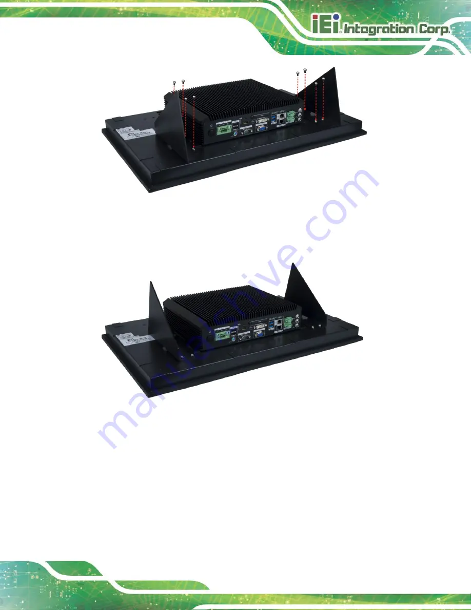
To display the S19A/S24A-QM87i at a different viewing angle, install the stand
mounting kit in the other way.
S
te
p
0
:
Figure 3-17: Stand Mounting Method 2
3.5.3 Ceiling Mounting
To mount the S19A/S24A-QM87i using the optional ceiling mounting kit, please follow the
steps below.
Step 1:
Select a location on the ceiling for the ceiling mounting brackets.
Step 2:
Refer to the dimensions listed in the following diagrams to mark the locations of
the six bracket screw holes on the ceiling.
Summary of Contents for S19A-QM87
Page 13: ...S19A S24A QM87i Marine Panel PC Page 1 Chapter 1 1 Introduction ...
Page 24: ...S19A S24A QM87i Marine Panel PC Page 12 Chapter 2 2 Unpacking ...
Page 28: ...S19A S24A QM87i Marine Panel PC Page 16 Chapter 3 3 Installation ...
Page 53: ...S19A S24A QM87i Marine Panel PC Page 41 Chapter 4 4 On Screen Display OSD Controls ...
Page 59: ...S19A S24A QM87i Marine Panel PC Page 47 Chapter 5 5 BIOS Setup ...
Page 97: ...S19A S24A QM87i Marine Panel PC Page 85 Chapter 6 6 Maintenance ...
Page 102: ...S19A S24A QM87i Marine Panel PC Page 90 Chapter 7 7 Interface Connectors ...
Page 104: ...S19A S24A QM87i Marine Panel PC Page 92 Figure 7 2 Main Board Layout Diagram Solder Side ...
Page 118: ...S19A S24A QM87i Marine Panel PC Page 106 Appendix A A Regulatory Compliance ...
Page 123: ...S19A S24A QM87i Marine Panel PC Page 111 Appendix B B Safety Precautions ...
Page 128: ...S19A S24A QM87i Marine Panel PC Page 116 Appendix C C BIOS Menu Options ...
Page 131: ...S19A S24A QM87i Marine Panel PC Page 119 Appendix D D Watchdog Timer ...
Page 134: ...S19A S24A QM87i Marine Panel PC Page 122 E Hazardous Materials Disclosure Appendix E ...

