S19A/S24A-QM87i-i5 Marine Panel PC
Page 28
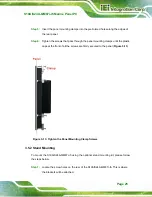
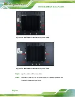
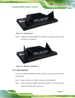
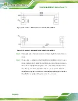
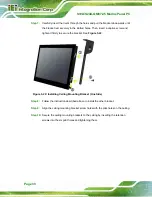
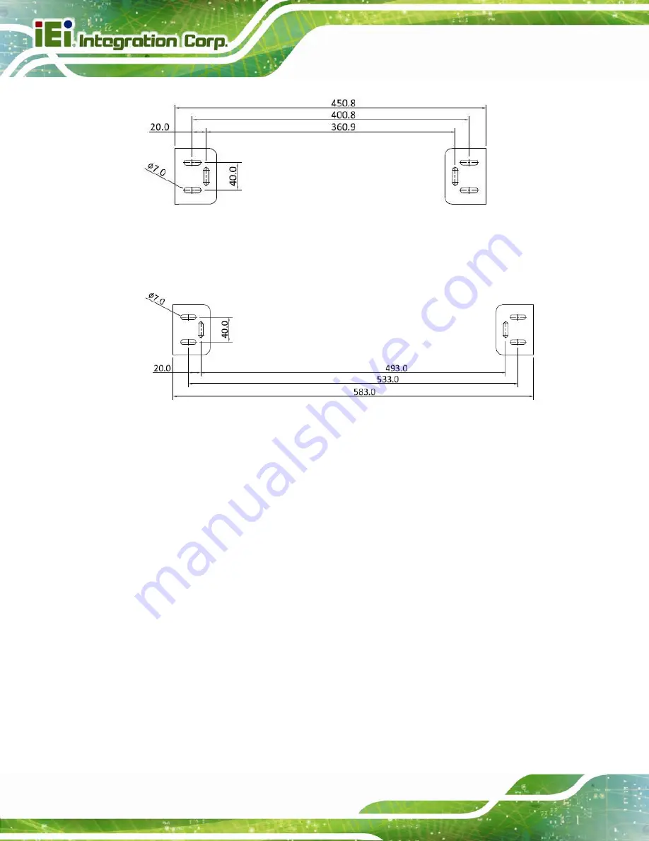
Figure 3-18: Locations of Bracket Screw Holes for S19A-QM87i
Figure 3-19: Locations of Bracket Screw Holes for S24A-QM87i
Step 3:
Drill six pilot holes at the marked locations on the ceiling for the bracket retention
screws.
Step 4:
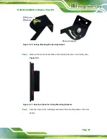
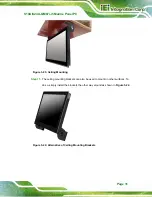
Please adjust the ceiling mounting brackets before installation in order to have a
proper viewing angle. To adjust the mounting angle, pull out the green screw on
the bracket and gently rotate the green screw to temperately lock the screw in
the pull-out position. Then, adjust the bracket to a proper position. When the
bracket almost reaches the ideal point, rotate the green screw again to release it.
Move the bracket gently until the green screw snap into place.
Summary of Contents for S19A-QM87i-i
Page 13: ...S19A S24A QM87i i5 Marine Panel PC Page 1 Chapter 1 1 Introduction ...
Page 24: ...S19A S24A QM87i i5 Marine Panel PC Page 12 Chapter 2 2 Unpacking ...
Page 28: ...S19A S24A QM87i i5 Marine Panel PC Page 16 Chapter 3 3 Installation ...
Page 53: ...S19A S24A QM87i i5 Marine Panel PC Page 41 Chapter 4 4 On Screen Display OSD Controls ...
Page 59: ...S19A S24A QM87i i5 Marine Panel PC Page 47 Chapter 5 5 BIOS Setup ...
Page 97: ...S19A S24A QM87i i5 Marine Panel PC Page 85 Chapter 6 6 Maintenance ...
Page 102: ...S19A S24A QM87i i5 Marine Panel PC Page 90 Chapter 7 7 Interface Connectors ...
Page 104: ...S19A S24A QM87i i5 Marine Panel PC Page 92 Figure 7 2 Main Board Layout Diagram Solder Side ...
Page 118: ...S19A S24A QM87i i5 Marine Panel PC Page 106 Appendix A A Regulatory Compliance ...
Page 123: ...S19A S24A QM87i i5 Marine Panel PC Page 111 Appendix B B Safety Precautions ...
Page 128: ...S19A S24A QM87i i5 Marine Panel PC Page 116 Appendix C C BIOS Menu Options ...
Page 131: ...S19A S24A QM87i i5 Marine Panel PC Page 119 Appendix D D Watchdog Timer ...
Page 134: ...S19A S24A QM87i i5 Marine Panel PC Page 122 E Hazardous Materials Disclosure Appendix E ...

