S19A/S24A-QM87i-i5 Marine Panel PC
Page 35
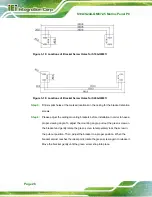
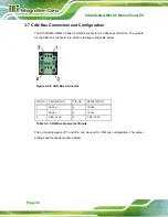
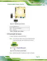
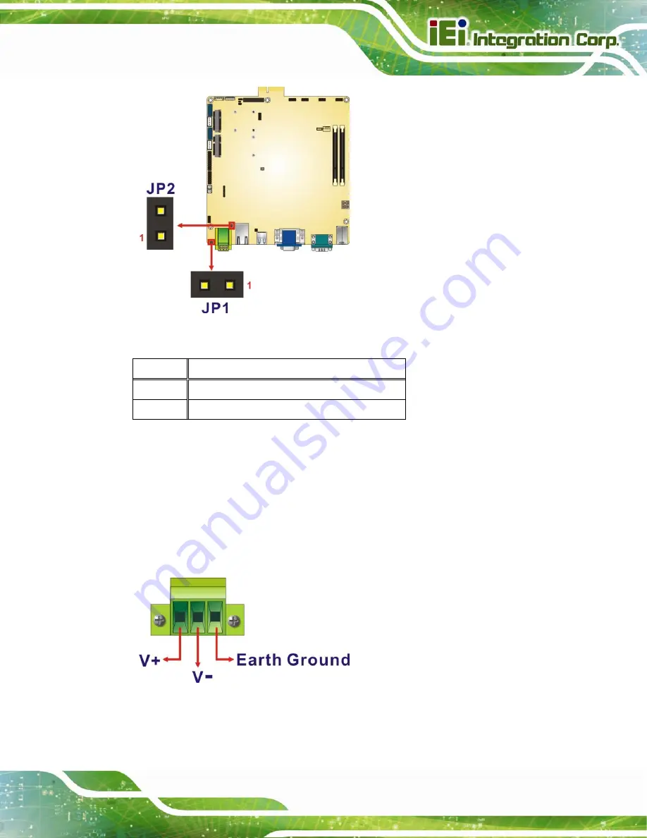
Figure 3-27: CAN Bus Jumper Locations
JP1 & JP2
DESCRIPTION
Short Long
wire
transmitting
Open Normal
Table 3-4: CAN Bus Jumper Settings
3.8 Powering On the System
To power on the system, follow the steps below:
Step 1:
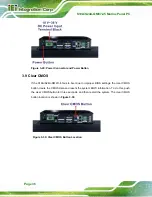
Connect the power cable to the 3-pin power input terminal block.
The pinouts of the power input connectors are shown below.
Figure 3-28: Power Input Connector Pinouts
Step 2:
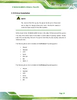
Push the power button on the I/O panel to power on the system.
Step 0:
Summary of Contents for S19A-QM87i-i
Page 13: ...S19A S24A QM87i i5 Marine Panel PC Page 1 Chapter 1 1 Introduction ...
Page 24: ...S19A S24A QM87i i5 Marine Panel PC Page 12 Chapter 2 2 Unpacking ...
Page 28: ...S19A S24A QM87i i5 Marine Panel PC Page 16 Chapter 3 3 Installation ...
Page 53: ...S19A S24A QM87i i5 Marine Panel PC Page 41 Chapter 4 4 On Screen Display OSD Controls ...
Page 59: ...S19A S24A QM87i i5 Marine Panel PC Page 47 Chapter 5 5 BIOS Setup ...
Page 97: ...S19A S24A QM87i i5 Marine Panel PC Page 85 Chapter 6 6 Maintenance ...
Page 102: ...S19A S24A QM87i i5 Marine Panel PC Page 90 Chapter 7 7 Interface Connectors ...
Page 104: ...S19A S24A QM87i i5 Marine Panel PC Page 92 Figure 7 2 Main Board Layout Diagram Solder Side ...
Page 118: ...S19A S24A QM87i i5 Marine Panel PC Page 106 Appendix A A Regulatory Compliance ...
Page 123: ...S19A S24A QM87i i5 Marine Panel PC Page 111 Appendix B B Safety Precautions ...
Page 128: ...S19A S24A QM87i i5 Marine Panel PC Page 116 Appendix C C BIOS Menu Options ...
Page 131: ...S19A S24A QM87i i5 Marine Panel PC Page 119 Appendix D D Watchdog Timer ...
Page 134: ...S19A S24A QM87i i5 Marine Panel PC Page 122 E Hazardous Materials Disclosure Appendix E ...

