S19A/S24A-QM87i Marine Panel PC
Page 79
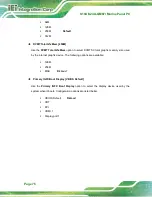
Launch PXE OpROM [Disabled]
Use the
Launch PXE OpROM
option to enable or disable boot option for legacy network
devices.
Disabled
D
EFAULT
Ignore all PXE Option ROMs
Enabled
Load PXE Option ROMs
UEFI Boot [Disabled]
Use the
UEFI Boot
option to enable or disable to boot from the UEFI devices.
Disabled
D
EFAULT
Boot from UEFI devices is disabled.
Enabled
Boot from UEFI devices is enabled.
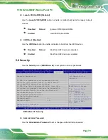
5.6 Security
Use the
Security
menu (
) to set system and user passwords.
Aptio Setup Utility – Copyright (C) 2012 American Megatrends, Inc.
Main
Advanced
Chipset
Boot
Security
Save & Exit Server Mgmt
Password Description
If ONLY the Administrator’s password is set,
then this only limits access to Setup and is
only asked for when entering Setup.
If ONLY the User’s password is set, then this
is a power on password and must be entered to
boot or enter Setup. In Setup the User will
have Administrator rights.
The password length must be
in the following range:
Minimum length
3
Maximum length
20
Administrator Password
User Password
Set Administrator
Password
---------------------
: Select Screen
↑
↓
: Select Item
Enter
Select
+ - Change Opt.
F1
General Help
F2
Previous Values
F3
Optimized Defaults
F4
Save & Exit
ESC Exit
Version 2.15.1236. Copyright (C) 2012 American Megatrends, Inc.
BIOS Menu 22: Security
Administrator Password
Use the
Administrator Password
to set or change a administrator password.
Summary of Contents for S19A/S24A-QM87i
Page 13: ...S19A S24A QM87i Marine Panel PC Page 1 Chapter 1 1 Introduction ...
Page 24: ...S19A S24A QM87i Marine Panel PC Page 12 Chapter 2 2 Unpacking ...
Page 28: ...S19A S24A QM87i Marine Panel PC Page 16 Chapter 3 3 Installation ...
Page 53: ...S19A S24A QM87i Marine Panel PC Page 41 Chapter 4 4 On Screen Display OSD Controls ...
Page 59: ...S19A S24A QM87i Marine Panel PC Page 47 Chapter 5 5 BIOS Setup ...
Page 97: ...S19A S24A QM87i Marine Panel PC Page 85 Chapter 6 6 Maintenance ...
Page 102: ...S19A S24A QM87i Marine Panel PC Page 90 Chapter 7 7 Interface Connectors ...
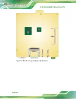
Page 104: ...S19A S24A QM87i Marine Panel PC Page 92 Figure 7 2 Main Board Layout Diagram Solder Side ...
Page 118: ...S19A S24A QM87i Marine Panel PC Page 106 Appendix A A Regulatory Compliance ...
Page 123: ...S19A S24A QM87i Marine Panel PC Page 111 Appendix B B Safety Precautions ...
Page 128: ...S19A S24A QM87i Marine Panel PC Page 116 Appendix C C BIOS Menu Options ...
Page 131: ...S19A S24A QM87i Marine Panel PC Page 119 Appendix D D Watchdog Timer ...
Page 134: ...S19A S24A QM87i Marine Panel PC Page 122 Appendix E E Hazardous Materials Disclosure ...


