TANK-610-BW Em b e d d e d S ys te m
P a g e 21
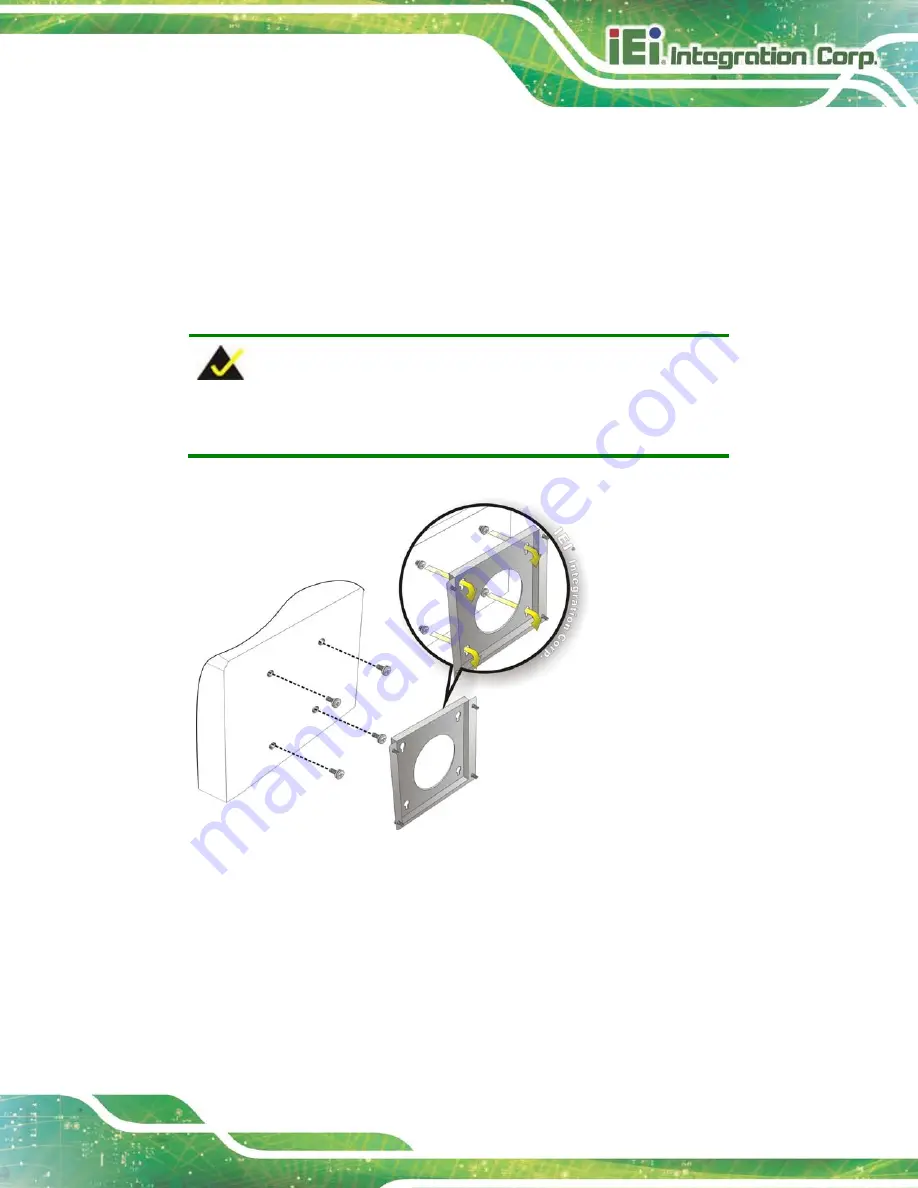
S te p 7:
Align the mounting screws on the TANK-610-BW bottom panel with the
mounting holes on the bracket.
S te p 8:
Carefully insert the screws through the holes and gently pull the monitor
downwards until the TANK-610-BW rests securely in the slotted holes (
). Ensure that all four of the mounting screws fit snuggly into their respective
slotted holes.
NOTE:
In the diagram below the bracket is already installed on the wall.
Figure 3-12: Mount the Embedded System
3.6
AT/ATX Mo d e S e le c tio n
AT or ATX power mode can be used on the TANK-610-BW. The selection is made
through an AT/ATX switch located on the bottom panel. To select AT mode or ATX mode,
follow the steps below.
S te p 1:
Locate the AT/ATX switch on the bottom panel (
).
Summary of Contents for TANK-610-BW
Page 11: ...TANK 610 BW Embedded Sys tem Page 1 Chapter 1 1 Introduction ...
Page 18: ...TANK 610 BW Embedded Sys tem Page 8 Chapter 2 2 Unpacking ...
Page 22: ...TANK 610 BW Embedded Sys tem Page 12 Chapter 3 3 Ins tallation ...
Page 41: ...TANK 610 BW Embedded Sys tem Page 31 Chapter 4 4 BIOS ...
Page 77: ...TANK 610 BW Embedded Sys tem Page 67 Appendix A A Regulatory Compliance ...
Page 83: ...TANK 610 BW Embedded Sys tem Page 73 B Safety Precautions Appendix B ...
Page 88: ...TANK 610 BW Embedded Sys tem Page 78 Appendix C C BIOS Options ...
Page 91: ...TANK 610 BW Embedded Sys tem Page 81 Appendix D D Terminology ...
Page 95: ...TANK 610 BW Embedded Sys tem Page 85 Appendix E E Hazardous Materials Dis clos ure ...


