TANK-620-ULT3 Embedded System
Page 34
A14
5VSYNC
B14
5VSYNC2
A15
5VDDCLK
B15
5VDDCLK2
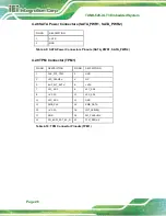
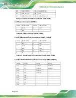
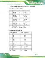
Table 4-20: VGA Connectors Pinouts (VGA_21)
4.4 Jumper Settings
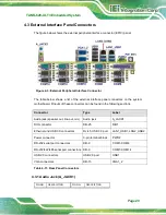
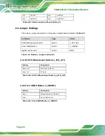
The buttons, jumper and switch on the system motherboard are listed in
Connector
Type
Label
AT/ATX Mode select switch
switch
J_ATX_AT1
Clear CMOS button
button
J_CMOS1
System reset button
button
RST1
Table 4-21: Buttons, Jumper and Switch
4.4.1 AT/ATX Mode Select Switch (J_ATX_AT1)
4.4.2 Clear CMOS Button (J_CMOS1)
Setting
Description
Short A-B
ATX Mode (Default)
Short B-C
AT Mode
Table 4-22: AT/ATX Mode Select Switch (J_ATX_AT1)
Setting
Description
Open
Normal Operation (Default)
Push
Clear CMOS Setup
Table 4-23: Clear CMOS Button (J_CMOS1)
Summary of Contents for TANK-620-ULT3
Page 12: ...TANK 620 ULT3 Embedded System Page 1 Chapter 1 1 Introduction ...
Page 19: ...TANK 620 ULT3 Embedded System Page 8 Chapter 2 2 Unpacking ...
Page 23: ...TANK 620 ULT3 Embedded System Page 12 Chapter 3 3 Installation ...
Page 34: ...TANK 620 ULT3 Embedded System Page 23 4 System Motherboard Chapter 4 ...
Page 47: ...TANK 620 ULT3 Embedded System Page 36 Chapter 5 5 BIOS ...
Page 94: ...TANK 620 ULT3 Embedded System Page 83 Appendix A A Regulatory Compliance ...
Page 99: ...TANK 620 ULT3 Embedded System Page 88 Appendix B B BIOS Options ...
Page 103: ...TANK 620 ULT3 Embedded System Page 92 Appendix C C Terminology ...
Page 107: ...TANK 620 ULT3 Embedded System Page 96 Appendix D D Safety Precautions ...
Page 112: ...TANK 620 ULT3 Embedded System Page 101 Appendix E E Digital I O Interface ...
Page 115: ...TANK 620 ULT3 Embedded System Page 104 Appendix F F Hazardous Materials Disclosure ...

